Hi guys,
I have a Denon amp that goes into protection after 20% volume increase. Up to 3Vpp on the output it works fine, then it fails.
This was after shorting the speakers' terminals.
The bias current goes up a lot when the volume is turned up - 90mV on the test points (with a dummy load). On the other channel it is stable - 11mV.
There is almost no access for measurements in assembled form.
Who are the most likely suspects? TR 512, 514, 518, 520?
Regards!
Attachments
I hope you mean shorting the amplifier input? Shorting the speaker outputs really should send an amp into protection!This was after shorting the speakers' terminals.
Unfortunately no. Namely the speakers' terminals, but somehow the final mosfet transistors survived.
What are the DC voltages at the speaker terminals with no input, no load and volume turned down?
What happens when you then turn up the volume (still with no load and no input)?
What happens when you then turn up the volume (still with no load and no input)?
What happens when you turn up volume with signal present but no load on the problem channel?
It would be normal to see increasing bias current if you apply signal with a load present.
Do you have a scope?
It would be normal to see increasing bias current if you apply signal with a load present.
Do you have a scope?
Does not go into protect, bias does not increaseWhat happens when you turn up volume with signal present but no load on the problem channel?
With an 8Ohm load bias increases much faster on the problem channel (I monitor both):
Volume min.: good ch - 9.7mV, bad ch - 9.6mV
Volume 9 o'clock: good ch - 10.1mV, bad ch - 24.6mV
Volume 9:30 o'clock: good ch - 13.7mV, bad ch - 62.6mV
Volume 10 o'clock: good ch - 22.9mV, bad ch - 134mV
Volume 10:20 o'clock: good ch - 30.2mV, bad ch - 194.8mV
Volume 10:30 o'clock: good ch - 34.1mV, bad ch - 227.6mV
Volume 10:40 o'clock: good ch - 39mV, bad ch - 292mV
Then goes in protect, sometimes earlier.
I replaced the output transistors and the problem remains.
Yes, I have scope.
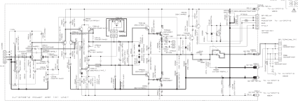
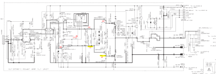
I am attaching the service manual.
Attachments
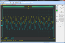
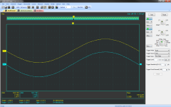
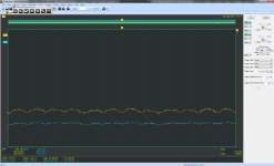
I suggest driving both channels with the same sine wave signal and comparing the two channels. Of course, increase drive cautiously. Be sure to use a x10 scope probe.
With luck, the scope will reveal the culprit. Let us know what you observe.
Good luck!
With luck, the scope will reveal the culprit. Let us know what you observe.
Good luck!
I didn't mention it, but I did the measurements above with 1Khz on both channels.
The two channels behave approximately the same and at 3.5-4Vpp it goes into protection.
Problem chanel is ch 1
The two channels behave approximately the same and at 3.5-4Vpp it goes into protection.
Problem chanel is ch 1
Attachments


I also changed the drivers TR518, 520, no change. I extended the cables and now there is good access for measuring.
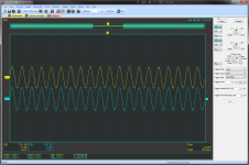
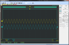
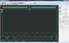
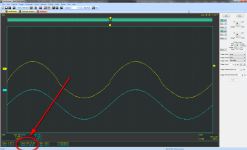
Try adjusting amplitude to about 3V pp and raise sweep speed to better study crossover behavior. Be sure to use DC coupling on scope to observe any shift in trace center as you vary amplitude—- there should be no shift in DC position vs. ampltude. Examine waveforms at bases of output and driver stages using working channel for reference. Remember x10 probes to minimize any tendency to oscillatio, especially re interstages.
If problem is protection triggering then let's study protection triggering.
In his amplifier TR526 detects high voltage across R558 meaning it detects high current.
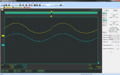
So start by scoping its Vbe.
You should see a positive half wave, measure its peak value.
Anything above some 650 mV will trigger it.
Use a fully floating scope input, because both terminals, Hot and scope "ground" follow speaker out signal.
Or use differential mode if your scope allows.
For such uses I bought a cheap ($25) 9V battery or class 2 wall wart powered mini scope at Al1B4b4 , invaluable for such tests.

Of course your current scope might be able to make such test.
After we make this vital first test, we can proceed further.
To save sometime also measure R558.
It should register practically a short, it might have blown open.
Or its solder pads or tracks could have been vaporized or cracked open, making the protection system trigger happy ... literally.
In his amplifier TR526 detects high voltage across R558 meaning it detects high current.
So start by scoping its Vbe.
You should see a positive half wave, measure its peak value.
Anything above some 650 mV will trigger it.
Use a fully floating scope input, because both terminals, Hot and scope "ground" follow speaker out signal.
Or use differential mode if your scope allows.
For such uses I bought a cheap ($25) 9V battery or class 2 wall wart powered mini scope at Al1B4b4 , invaluable for such tests.
Of course your current scope might be able to make such test.
After we make this vital first test, we can proceed further.
To save sometime also measure R558.
It should register practically a short, it might have blown open.
Or its solder pads or tracks could have been vaporized or cracked open, making the protection system trigger happy ... literally.
bad ch 1
_______________edit
When measuring the Vbe of the TR526 the protection is immediately switched on.
R558 is OK
_______________edit
When measuring the Vbe of the TR526 the protection is immediately switched on.
R558 is OK
Attachments

Last edited:
Short pins 3 and 4 on CX056 when testing; leave the output open. You have to remove & check each BJT carefully - the multimeter will do here. The MOSFETs will need a tester, to check... they are tricky things. If the gate capacitive barrier is slightly damaged, it will cause oscillations, but the MOSFET will measure okay with a multimeter. Use a grounded wristband.
Ch1 has oscillations visible on the oscilloscope trace. It looks like a non-linear device issue to me (a diode problem). Either that, or you still have either BJT or MOSFET issue.
I'd replace all diodes, including Zeners.
Ch1 has oscillations visible on the oscilloscope trace. It looks like a non-linear device issue to me (a diode problem). Either that, or you still have either BJT or MOSFET issue.
I'd replace all diodes, including Zeners.
Hi guys,
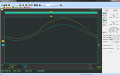
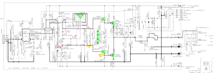
I have time left for this repair. It seems the problem is around the base of the TP516(515). I use the schematic of the good channel because it has the voltages marked on it.
I have time left for this repair. It seems the problem is around the base of the TP516(515). I use the schematic of the good channel because it has the voltages marked on it.
Attachments
Did you adjust bias after replacing parts? (Page 3 of SM, no load)
Where did you purchase the parts?
Where did you purchase the parts?
Yes, I did bias adjustment. The parts are certainly original, but the fact that there is no change in the behavior of the problem tells me that the ones I removed were ok too.
Did you have any luck with your problem?
I took a closer look at the math and detail it below.
For simplicity I’m assuming pure class B with sine wave signals, so the current in TR523 will be the positive half cycle and 0 current during the negative half cycle. In a half cycle sine wave with peak Vpk, the average voltage is 2Vpk/Pi, so the average voltage over a full cycle is:
Va = Vpk/Pi or alternately Vpk = Va*Pi. *
In post 8, you observed a bias voltage in bad channel of 292mV. This would correspond to a Vpk of 0.917V across R557. The corresponding current is 9.17A peak. Assuming this peak current produces a clean sine wave, the output power would be about 336W into 8 ohms.
I doubt this output power is really delivered, but if the sensed drain current is roughly correct, that current must be going somewhere. I’m guessing into TR523, so it and TR519 would be my favorite suspects. I would imagine that the two FETs should be getting equally hot, and hotter than the good channel.
Good luck!
* If there’s any doubt about the meter measuring average voltage, you could form a low pass filter by tacking a 100nF cap across TP501 pins 1 and 3.
- Home
- Amplifiers
- Solid State
- Protection after volume increase