No success so far. Many thanks for the detailed post. I will continue as soon as possible.
Cheers!
Cheers!
would you try to check input fets, differential input.
Maybe your feedback fet in differential pair is damaged (TR504), I will suspect on that.
To me the voltage which is marked as +57V (sm schematic) on negative side of output fet is not correct. What did you measured is correct, -60V.
Maybe your feedback fet in differential pair is damaged (TR504), I will suspect on that.
To me the voltage which is marked as +57V (sm schematic) on negative side of output fet is not correct. What did you measured is correct, -60V.
I don't notice a difference in the temperature of the two radiators.I doubt this output power is really delivered, but if the sensed drain current is roughly correct, that current must be going somewhere. I’m guessing into TR523, so it and TR519 would be my favorite suspects. I would imagine that the two FETs should be getting equally hot, and hotter than the good channel.
I use several multimeters and the voltage is always like this.If there’s any doubt about the meter measuring average voltage, you could form a low pass filter by tacking a 100nF cap across TP501 pins 1 and 3.
I replaced the input fets as well as many others (marked in green) but no improvement. I'm getting desperatewould you try to check input fets, differential input.
Attachments
Replace D514. Are R560 and R568 okay?
Do you still have protection kicking in when you place the probe on the base of TR526? Is the probe set to 10:1? This might be expected behaviour.
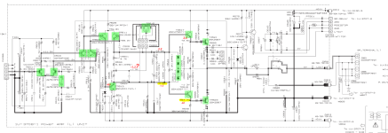
That area is very prone to oscillations; notice the R562 and R564 in series with the bias measurement points. Also, notice the output filter is omitted (L502 open; R592 short)
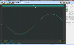
Can you show this section again circled in red, repeat the measurements, increase the time base... and use AC coupling? Show both channels again; load them the same.

Do you still have protection kicking in when you place the probe on the base of TR526? Is the probe set to 10:1? This might be expected behaviour.
That area is very prone to oscillations; notice the R562 and R564 in series with the bias measurement points. Also, notice the output filter is omitted (L502 open; R592 short)
Can you show this section again circled in red, repeat the measurements, increase the time base... and use AC coupling? Show both channels again; load them the same.
Last edited:
You measure a few hundred mV at TP501, yet nothing gets hot. It would seem that no current is really flowing through R558. I suspect an open PCB trace that’s very difficult to find since R558 is only 0.1 ohm. With power off, measure resistance from drain of TR523 to source of TR521. Should be about 0.1 ohm.
Sorry, I'm managing to mix Ref Des across the two channels. You measure 292mV at TP502, correct? So I intended resistance measurement from drain of TR524 to source of TR522. Try to measure directly at the transistor leads so that continuity through all series traces and components is exercised.
D514 has been changed, R560, R568 and the tracks between are checked - same storyReplace D514. Are R560 and R568 okay?
on the base of TR526 the input signal 1kHz can be monitored (Gnd probe is attached to the common ground CX016)Do you still have protection kicking in when you place the probe on the base of TR526? Is the probe set to 10:1? This might be expected behaviour.
I think this is on the outputCan you show this section again circled in red, repeat the measurements, increase the time base... and use AC coupling? Show both channels again; load them the same.
now, after so many replacement, he didn't go in protect up to 13Vpp and 400mV on TP502 (in this time on the good channel TP501 29.5mV) and i stop increase volume.
weird, I measure 0.8 - 1 Ohm / on the good channel full short 0.0 OhmSo I intended resistance measurement from drain of TR524 to source of TR522. Try to measure directly at the transistor leads so that continuity through all series traces and components is exercised.
Attachments
I believe you’re in the problem spot if you’re finding about 1 ohm when it should be 0.1 ohm. As an unpowered sanity check, install a wire short across the leads of R558 and remeasure resistance. Should tell us something.
You can't see me, but I'm doing the victory dance right now 😀
That seems to have been the problem. I replaced that resistor and boosted to 40Vpp with no protect.
I'll wait for my euphoria to wear off and put together the amp for further testing, but I believe the problem has been found with the invaluable help of BSST, Extreme_Boky and everyone else who wrote in the thread.
Respect!
Last edited:

- Home
- Amplifiers
- Solid State
- Protection after volume increase