I own several Behringer Inuke Amps.
I would like to know if it is possible to transform these powerful amps to current drive?
Maybe someone has the experience to read the schematic and tell if there is any chance to do this. If not is there a powerful class D amplifier usable for this instead?
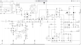
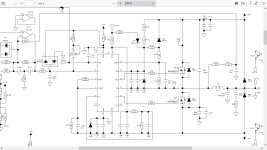
I added here part of the schematic where the input and output can be examined.
And the complete schematic as PDF.
Initial information on this type of amplifiers:
https://www.current-drive.info/
I managed succesfully - although I am not into electronics - to make small amps based on TDA2003 - with great sonic benefits with fullrange drivers without crossover.
Watch here: https://www.diyaudio.com/community/...n-to-current-drive.389985/page-7#post-7225986
Result was great sonic benefit like better bass, better mids, better highs - more bass and more highs. Everything sounds much more undistorted.
What is nice is that cheap fullrange drivers without copper/faraday ring profit more from this amplifier modification than already good drivers.
99% of all loudspeakers worldwide sold are the cheap ones - not the sophisticated and elaborated.
However what lacks is a beefy amplifier wich can put out several hundreds of watts so you can drive any loudspeaker.
For this I visited here the class D amplifier section.
It would be enough to change the schematic to "basic current feedback" as Esa Merilainen describes it:
https://www.current-drive.info/9
I would like to know if it is possible to transform these powerful amps to current drive?
Maybe someone has the experience to read the schematic and tell if there is any chance to do this. If not is there a powerful class D amplifier usable for this instead?
I added here part of the schematic where the input and output can be examined.
And the complete schematic as PDF.
Initial information on this type of amplifiers:
https://www.current-drive.info/
I managed succesfully - although I am not into electronics - to make small amps based on TDA2003 - with great sonic benefits with fullrange drivers without crossover.
Watch here: https://www.diyaudio.com/community/...n-to-current-drive.389985/page-7#post-7225986
Result was great sonic benefit like better bass, better mids, better highs - more bass and more highs. Everything sounds much more undistorted.
What is nice is that cheap fullrange drivers without copper/faraday ring profit more from this amplifier modification than already good drivers.
99% of all loudspeakers worldwide sold are the cheap ones - not the sophisticated and elaborated.
However what lacks is a beefy amplifier wich can put out several hundreds of watts so you can drive any loudspeaker.
For this I visited here the class D amplifier section.
It would be enough to change the schematic to "basic current feedback" as Esa Merilainen describes it:
https://www.current-drive.info/9
Attachments
Last edited:
current feedback (citation from Merilainen website)
Figure b shows, correspondingly, the use of current-feedback* in its simplest form. Again, the non-inverting input terminal acts as the input, but now the feedback signal applied to the inverting terminal reflects the current flowing through the load (Io), instead of the load voltage.

Figure b shows, correspondingly, the use of current-feedback* in its simplest form. Again, the non-inverting input terminal acts as the input, but now the feedback signal applied to the inverting terminal reflects the current flowing through the load (Io), instead of the load voltage.
Nonsense.Result was great sonic benefit like better bass, better mids, better highs - more bass and more highs. Everything sounds much more undistorted.
What is nice is that cheap fullrange drivers without copper/faraday ring profit more from this amplifier modification than already good drivers.
99% of all loudspeakers worldwide sold are the cheap ones - not the sophisticated and elaborated.
The answer to your query is...no, you can't modify your Inuke.
Just add a series resistor to the output.
Dave.

Class D is not the place to start ... 😵although I am not into electronics
Is there any technical solution for marrying a class D amp with current drive principle?
Maybe cfa OP amp controlling amplifier current?
Maybe cfa OP amp controlling amplifier current?
For triangle wave PWM the concept is quite simple. I see no reason why it might be extended to a self-oscillating set up but that might be a bit harder although adding a delay to the invertor might send it over the edge.
One thing you have to do in the triangle case is implement slope matching. The zero demand ripple current converted to a voltage in the sense resitor is a triangle wave. You set the gain, R2/R1, in the CEA so it is half the amplitude of the pwm triangle wave. The crossover frequency will be FS/pi, 127K in this case. You pick C2 to form a zero with R2 at half this frequency.
Have a play.
Attachments
Last edited:
Wow, sounds great. For me I cannot follow but with your proposition I can ask someone educated in electronics to make the change.
Class D amps are VERY different from classic "analog" amps which can be seen as "BIG Op Amps"Is this generally the case with class D amps?
In away, that might work.Is there any technical solution for marrying a class D amp with current drive principle?
Maybe cfa OP amp controlling amplifier current?
You are not modding the Class D amp itself, but you may sample output current, generate a signal, and use that to control a gain stage before the big amp, which you use only as "muscle".
That's the idea.
I have been thinking about it because I make guitar amps, which uses mixed feedback to approach Tube sound.
Easy on Class AB amps, not at all on Class D ones.
Not aware of anybody doing that today.
I have been thinking about it because I make guitar amps, which uses mixed feedback to approach Tube sound.
Easy on Class AB amps, not at all on Class D ones.
Not aware of anybody doing that today.
Some more thoughts on this.
Whilst I have given a couple of suggestions as to how it might be implemented those involve the complete rework of or construction of a new amplifier. Ideally you just want to tag something around what is a self oscillating amplifier that is using what would be termed voltage mode control.
Self oscillation with voltage mode control relies on the second order nature of the output filter, and added phase shifts in the control loop along with perhaps intrinsic switching delays, in order to achieve that oscillation at some output switching frequency range. You will have a feedback resistor, or network, from the output of the amplifier to the input of the main, first voltage error amplifier. There may also be an additional loop from the output injecting ripple into the control loop at a later stage.
Fine. So that works.
All current mode control does is reduce the order of the output filter by one. It converts the output inductor into a current source, over frequencies of interest. So instead of feeding back from the output voltage terminal you feedback from the top of your current sense resistor but in order to make it work again you have to put the pole you removed back in again. Conceptually that would simply mean, assuming you get the +/- feedback correct, inserting an integrating op-amp into your current feedback loop.
In effect current feedback removes a pole and the integrator puts it back in. If you analyse the voltage feedback and ripple to determine its value at the input to the first amplifier then select the feedback capacitor in your integrator based on the inductor ripple current converted to a ripple voltage in the sense resistor of the same value then you should maintain the same loop response that the original amplifier had and it should work as before.
Would be great if someone finds out how to realize a schematic converting any voltage driven amplifier into a current driven one.
@Freedom666 I think you're still confused on the whole topic since you're flopping the terms around haphazardly.
I suggest to read up before thinking about possibly converting a topology from one to the other. 🙂
The simplest "conversion" is as I mentioned up on Post #4. And even that is a ****-poor one.
Dave.
I suggest to read up before thinking about possibly converting a topology from one to the other. 🙂
The simplest "conversion" is as I mentioned up on Post #4. And even that is a ****-poor one.
Dave.
Like mentioned above, a good place to start could be to add series resistance directly to the speaker. Say, 10 or 22 ohms and, if necessary, adjust the EQ back to a preferred level. While this reduces efficiency, finding significantly over-powered modules shouldn't really be a problem, and with Ohm's law you can find the total power dissipation.Is there any technical solution for marrying a class D amp with current drive principle?
Maybe cfa OP amp controlling amplifier current?
With a 100W module and 22 ohms in series, from the speaker's POV it'll be about 7W, with about 20W of waste heat in the resistor (maybe 40W if you're using the amplifier as a square wave effects pedal, but with undistorted usage a 5W resistor probably won't even get warm).
Sounds like Davey is throwing down the guantlet. Fortunately it's not my amplifier so proceed at your own peril.
Whatch out for my big mistake!1!
Looking at the circuit provided for the NU3000 for the upper channel the controlling amplifier is IC17. It has a simple 47K (R130) from the output via two 750R resistors with a 56pF capacitor. Those last three make a filter at 1.9MHz and are probably there for noise supression.
It suposedly does 2x1500W into two ohms so that is 27.5A RMS. Let's say you can throw away 5 Watts in your current sense resistor. You'll need 6.66mR. Of course you'll have to parallel a bunch of non-inductive metal film things. Ignoring the snubber on the output the filter is 22u and 470n and you have 78V rails. At zero output that is going to stick a 160V p-p square wave into the output filter at the self oscillating frequency. Call that 440KHz.
Feedback is to the inverting input of IC17 which will, supposedly, act as a virtual ground when the loop is active. You can see that sometimes that might not happen so they have thrown in some limiting diodes.
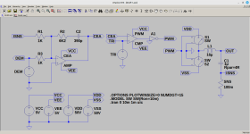
We get one of these..

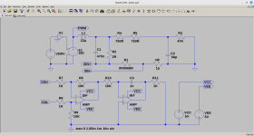
VDRV is a 440KHz sine wave converted to a square wave by A1 (+/-1V) amplified by E1 to +/-160V which drives the output filter. We plot the ripple current in R3. We also plot the ripple voltage, a triangle wave, at ISNS.
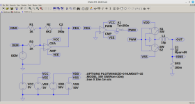
Now we throw in some amplifiers. One is a differential amplifier with inputs ISN+ and ISN- across your current sense resistor. This is to take out trace, wire resistances. [Pay special attention to how you install your current sense resistor and the differential amplifier]. Take care with that one. The other is the previously mentioned integrator with some values thrown in. We get this.

Which does this.

Notice that the waveforms for currents in R3 and R11 match each other. The amplitudes are slightly different but if we adjust R11 to 1K6 we can make them the same.

The big mistake is I have not taken into account the input sensitivity of the amplifier. This is quoted as being 0.755V but we can probably approach it from a different direction. Your peak output voltage is about 80V which in 2R is about 40A. 80V across 47K is 1.7mA. 40A in your 6.8mR sense resistor is 0.272V times 10 for the diff amp is 2.72V which is 1.7mA. I am slightly surprised. The numbers match.
Silly me. They would. No worries then.
So. That's more or less it. As suggested current mode control removes the inductor pole. The integrator puts it back in again and you match the feedback ripple currents to maintain the behaviour of the original control loop.
In respect of those two amplifiers you will most likely have to use something with a decent gain bandwidth product. If you make R6, R9 and R10 3K3 in my circuit then it will split the gain between the two amplifiers. 5MHz?
Oh. Also notice how the diff amp inverts and then the integrating amp also inverts which maintains the sense of your feedback.
Whatch out for my big mistake!1!
Looking at the circuit provided for the NU3000 for the upper channel the controlling amplifier is IC17. It has a simple 47K (R130) from the output via two 750R resistors with a 56pF capacitor. Those last three make a filter at 1.9MHz and are probably there for noise supression.
It suposedly does 2x1500W into two ohms so that is 27.5A RMS. Let's say you can throw away 5 Watts in your current sense resistor. You'll need 6.66mR. Of course you'll have to parallel a bunch of non-inductive metal film things. Ignoring the snubber on the output the filter is 22u and 470n and you have 78V rails. At zero output that is going to stick a 160V p-p square wave into the output filter at the self oscillating frequency. Call that 440KHz.
Feedback is to the inverting input of IC17 which will, supposedly, act as a virtual ground when the loop is active. You can see that sometimes that might not happen so they have thrown in some limiting diodes.
We get one of these..
VDRV is a 440KHz sine wave converted to a square wave by A1 (+/-1V) amplified by E1 to +/-160V which drives the output filter. We plot the ripple current in R3. We also plot the ripple voltage, a triangle wave, at ISNS.
Now we throw in some amplifiers. One is a differential amplifier with inputs ISN+ and ISN- across your current sense resistor. This is to take out trace, wire resistances. [Pay special attention to how you install your current sense resistor and the differential amplifier]. Take care with that one. The other is the previously mentioned integrator with some values thrown in. We get this.
Which does this.
Notice that the waveforms for currents in R3 and R11 match each other. The amplitudes are slightly different but if we adjust R11 to 1K6 we can make them the same.
The big mistake is I have not taken into account the input sensitivity of the amplifier. This is quoted as being 0.755V but we can probably approach it from a different direction. Your peak output voltage is about 80V which in 2R is about 40A. 80V across 47K is 1.7mA. 40A in your 6.8mR sense resistor is 0.272V times 10 for the diff amp is 2.72V which is 1.7mA. I am slightly surprised. The numbers match.
Silly me. They would. No worries then.
So. That's more or less it. As suggested current mode control removes the inductor pole. The integrator puts it back in again and you match the feedback ripple currents to maintain the behaviour of the original control loop.
In respect of those two amplifiers you will most likely have to use something with a decent gain bandwidth product. If you make R6, R9 and R10 3K3 in my circuit then it will split the gain between the two amplifiers. 5MHz?
Oh. Also notice how the diff amp inverts and then the integrating amp also inverts which maintains the sense of your feedback.
Attachments
Last edited:
I'm not laying down any gauntlet. I'm just saying let's stop playing fast and loose with the words and definitions.
It's not difficult to build a transconductance amplifier. I would be difficult to convert an existing Class-D voltage source to become one.
From a practical standpoint, I'm not sure what the point of that would be.
Build yourself a Pass F1 instead. A lot more fun and a lot better result.
Dave.
It's not difficult to build a transconductance amplifier. I would be difficult to convert an existing Class-D voltage source to become one.
From a practical standpoint, I'm not sure what the point of that would be.
Build yourself a Pass F1 instead. A lot more fun and a lot better result.
Dave.
- Home
- Amplifiers
- Class D
- Behringer Inuke NU3000 current drive modification