I took a few measurements using REW and a decent microphone. I had the mic within an inch of the speaker.
The image with 50 Hz near the bottom of the Y axis shows music playing in red and the white is 120Hz hum.
The other image with 50 Hz near the bottom of the Y axis is with no music playing.
For the other images I expanded the Y axis, had no music playing, and moved the microphone away from the speaker.
Attachments
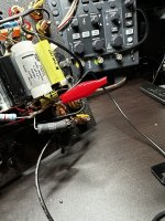
Adding the inductor did not make a difference in the hum. I will need to start looking at other causes.
If the cause is power supply ripple then that choke should have at least reduced it right?
If the cause is power supply ripple then that choke should have at least reduced it right?
Attachments
Last edited:
If the power supply ripple was the main cause, adding additional filter capacitance would have had an effect as well, so no surprise that adding the choke had no effect.
Time to try the other things suggested.
Time to try the other things suggested.

How does the microphone signal get to REW?I took a few measurements using REW and a decent microphone. I had the mic within an inch of the speaker.
The USB interface may have a 1Megohm unbalanced instrument input socket - and be USB powered - if so then you have some relatively simple options for making measurements using REW. The main action is to make a 100:1 resistive divider that connects to your amp's speaker terminals and attenuates that voltage down to a level where it won't damage or clip the interface's input circuitry. I use a 100:1 oscilloscope probe, but a 1k and 100k resistor would do the same job. If you have a laptop (rather than a mains powered PC) then that is even better as it avoids your amp from interacting with the soundcard and showing up stray hum-loop signals.
This form of measurement is very common nowadays for amp assessment and provides a nice clean view of your amps output - rather that using your microphone and picking up a lot of room/ambient noise in the REW plot.
This form of measurement is very common nowadays for amp assessment and provides a nice clean view of your amps output - rather that using your microphone and picking up a lot of room/ambient noise in the REW plot.
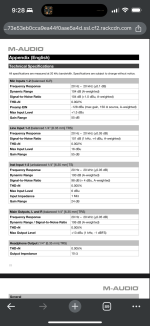
The USB audio interface is an M-Audio MTrack 2x2M. USB powered.
Would I build something like in the attached image where R1 is 100k and R2 is 1k ? Would P1 connect to the speaker terminal of the amp, P2 to ground, and P3 to the audio interface input?
Would I build something like in the attached image where R1 is 100k and R2 is 1k ? Would P1 connect to the speaker terminal of the amp, P2 to ground, and P3 to the audio interface input?
Attachments
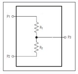
Yes that's the general concept - P2 is also the gnd for the unbalanced input to the interface. You need to check how to connect/enable the 1Mohm input mode of your interface.
Lots of threads on interfacing issues and how to make measurements - such as https://www.diyaudio.com/community/threads/how-to-distortion-measurements-with-rew.338511/. Use a meter to confirm AC voltage at amp output is relatively low, and that attenuated signal going to interface is about 1% of that level. Then raise up amp output (with speaker or dummy load) and confirm signal level presented to interface is well below 1V - that should reduce risk that you could overload the interface - but there is always risk!
Lots of threads on interfacing issues and how to make measurements - such as https://www.diyaudio.com/community/threads/how-to-distortion-measurements-with-rew.338511/. Use a meter to confirm AC voltage at amp output is relatively low, and that attenuated signal going to interface is about 1% of that level. Then raise up amp output (with speaker or dummy load) and confirm signal level presented to interface is well below 1V - that should reduce risk that you could overload the interface - but there is always risk!
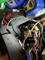
The center tap of the transformer winding that powers the tube filament heaters is directly connected to the same point as the audio ground, where the negatives of the RCA inputs are connected. Would it be better to move that center tap connection? I see some designs ground that through resistors.
Hi,If the power supply ripple was the main cause, adding additional filter capacitance would have had an effect as well, so no surprise that adding the choke had no effect.
Time to try the other things suggested.
I just wanted to check if this is what you meant when saying move the audio ground stand-off to the negative of the last filter cap.
Attachments
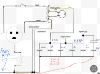
This is what I would try. I would take the ground for the output tubes from the negative of CapB. The positive to the output transformers should be twisted with the ground wire to the output tubes. This minimizes the loop areas to reduce hum pickup.
The ground for the input circuitry would come from the last capacitors and likewise, the power to the input tubes should be twisted with the ground wire. The input grounds should follow the signal wire to the input tube and connect to the ground there.
I think the ground for the filament centre-tap should be at the input ground, also. I could be wrong, but that is easy to change. All filament wiring should be twisted together to minimize loop areas as well.
Attachments
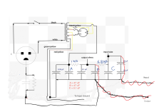
Thinking about this some more, what I've drawn, with two ground wires, may actually produce a signal ground loop between the input and output circuits. Might be better to just use one ground wire from the last capacitors to the input and output circuits and twist all the wires together. Or try both ways and see if one is better.
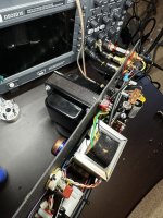
A lot depends on the actual physical layout of your amp. From what I've seen, it looks really tight, which in itself causes problems since physical distance is good for reducing AC hum.
A lot depends on the actual physical layout of your amp. From what I've seen, it looks really tight, which in itself causes problems since physical distance is good for reducing AC hum.
I forgot to mention, when I spoke with the Amp Designer he said that with the output tubes not installed I should not hear anything from the speakers, but I do hear the same hum. He had me try grounding the negative speaker terminals to a bolt on the transformer, which made no difference.
Also, I turned the amp on after lifting the first resistor (1k) in the power supply, and the hum through the speakers is still present. Is this telling me anything?
Also, I turned the amp on after lifting the first resistor (1k) in the power supply, and the hum through the speakers is still present. Is this telling me anything?
Last edited:
I may have found the reason that the amp hums. It seems like what trobbins was describing.
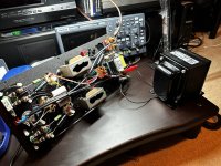
I removed the bolts holding on one of the output transformers. As I moved the OT away from the chassis and power transformer the hum from the speaker reduced. I could not move it very far because of the short wires.
I removed the bolts holding on one of the output transformers. As I moved the OT away from the chassis and power transformer the hum from the speaker reduced. I could not move it very far because of the short wires.
Attachments
It looks like you have adequately excluded direct B+ connection to the OPT as a transfer path for your observable hum, and are starting to assess how remote field coupling is the transfer path.
Field coupling is typically affected by separation distance, geometric orientation of the transformers, and any metallic shields/bell-ends or flux bands in and around the transformers.
For the purposes of assessment, I can see that moving one of the OPT's may be the easiest single change to check what difference occurs. Temporary extension of one or more leads from an OPT may give enough slack to physically move the OPT to a few different situations - where distance from the PT, and rotation in x, y, z planes may give some discernible benefit. It looks like separation distance, by inserting stand-offs, may be a practical final outcome?
Adding metallic shields may be a bit more hit and miss, as the coupled frequency is low (mains Hz), and material type (steel, mu-metal, ...), and thickness, and shape/location may all have some influence.
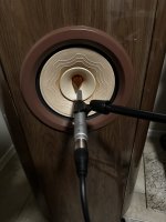
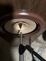
I made a cable today and attempted to measure the output of the amp using my audio interface and REW. I could not get anything to show up in REW.
I connected the home made cable in parallel with the speaker connections. 8 ohm speakers were connected to L & R outputs while I was attempting to measure.
I verified that the correct audio device was selected, and tried both L & R channels in REW settings.
I verified the home made cable using my DMM.
I did not measure any AC on the TS plug, or at the speaker outputs though. I think that the DMM that I have is only sensitive down to 600mV. It is a Kaiweets HT118A.
Is it possible that the signal is being attenuated too much? The most that this amp is capable of outputting is 2.3 Watts.
Attachments
Last edited:
Can you achieve a loopback response with your interface and REW, in order to confirm channel selection ? Can you vary input and output signals for that loopback and obtain reasonable undistorted tone signal and what its voltage can reach, and also confirm the noise floor is say -100 to 120dB below the tone peak ?
I am able to using the output and input of the M-TRACK, but it only seems to work one time, then I need to restart REW for it to work again. This is using the 'Generator' in REW, and measuring using 'RTA' or 'levels'.
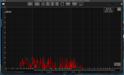
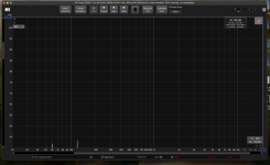
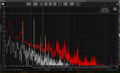
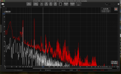
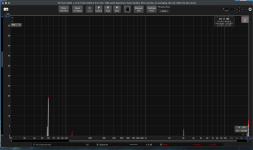
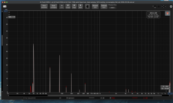
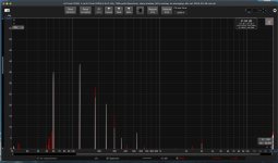
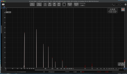
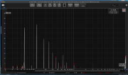
This time I was able to get some measurements. Attached are screenshots showing:
Amp off
No Audio Tubes Installed
Only Output Tubes Installed
Both Input and Output Tubes Installed
I had the output of the amplifier plugged into the 1/4 inch combo input on the back with the home made TS cable, in that configuration I believe that the max gain of that input is 6 dBu.
I am not sure how much the output of the amp was attenuated though.
Attachments
-
 Amp Off - Screenshot 2024-02-26 at 7.13.51 PM.png94.4 KB · Views: 32
 -
 No Audio Tubes - Screenshot 2024-02-26 at 7.12.26 PM.png113.7 KB · Views: 33
 -
 No Audio Tubes - Screenshot 2024-02-26 at 7.11.58 PM.png184.2 KB · Views: 38
 -
 Output Tubes In - Screenshot 2024-02-26 at 7.16.30 PM.png93.3 KB · Views: 31
 -
 Output and Input Tube In - Screenshot 2024-02-26 at 7.18.06 PM.png93.1 KB · Views: 30
 -
 All Tubes In and Gain Raised a bit on SoundCard - Screenshot 2024-02-26 at 7.19.22 PM.png101.9 KB · Views: 31
Perhaps re-read the how-to thread I linked before - and confirm the driver etc details. But yes, connect and select an 'output', and wire it to an 'input', and play with interface levels (not REW 'levels'). RTA is best to give a spectrum, and has lots of options/setup to get your head around, and then try and make some measurement sweeps. This is a steep learning curve for many - so try and use tutorials and threads to make it easier.
- Home
- Amplifiers
- Power Supplies
- Add LC Filter / Choke