Clever idea!If you are worried about RFI, you could cut the PCB antenna trace on the ESP32 board and solder on some thin coax and run to a short 1/4 wave antenna outside of the box. Probably a good idea to get good connectivity range anyhow
That's true alright haha. Unfortunately, my past experience with interference has told me to minimise the risks as much as possible. RFI/EMI from lights, computers and USB power supplies have all been issues I've dealt with/am dealing with. When it comes to guitar amps, I play prog rock/metal with anywhere from crispy cleans to crushing distortion, meaning I also have to contend with inter-harmonic distortion that could easily cause a not-so-serious set of noises even past human hearing range to really balloon out of proportion.I don't think you'll have troubles otherwise, lets face it - you don't hear Wifi RFI on you laptop speakers do you?
Since we're already using a micro, a holistic approach could be to tightly integrate the PSU into the design. Of course a common approach is use a bulky mains frequency transformer, which necessitates a large capacitor bank -- which then causes problems.
PSU design would be a sizeable project in its own right, but it seems feasible to have fast current sensing on the primary side, and if it ever exceeds some unwanted level, it can also be switched off quickly.
If Nelson Pass and others can build good-sounding amplifiers like the M2/M2x where push-pull MOSFETs are driven by JFETs with step-up, which reduces current capability even more, then it goes to show most VAS circuits are likely a waste of time.
But I'm also eyeing something more like an F1 style output stage. The tail CCS looks like a golden opportunity to tame the idle power with a supervisory micro -- use an 8-12 bit ADC to watch the input signal, and adjust things accordingly.
PSU design would be a sizeable project in its own right, but it seems feasible to have fast current sensing on the primary side, and if it ever exceeds some unwanted level, it can also be switched off quickly.
Rolling my own. The 'best' is one that actually gets finished and built! 95% of my ideas fizzle out -- but I'm a little bit giddy about this one.What design are you using for this? Just out of curiosity. I want to build a solid-state output that behaves like a tube power section, and I'm, "shopping around," for the best DIY project haha
If Nelson Pass and others can build good-sounding amplifiers like the M2/M2x where push-pull MOSFETs are driven by JFETs with step-up, which reduces current capability even more, then it goes to show most VAS circuits are likely a waste of time.
But I'm also eyeing something more like an F1 style output stage. The tail CCS looks like a golden opportunity to tame the idle power with a supervisory micro -- use an 8-12 bit ADC to watch the input signal, and adjust things accordingly.

I wonder how that would sound as a guitar amp 🤣If Nelson Pass and others can build good-sounding amplifiers like the M2/M2x
Ooo that does sound very cool!But I'm also eyeing something more like an F1 style output stage. The tail CCS looks like a golden opportunity to tame the idle power with a supervisory micro -- use an 8-12 bit ADC to watch the input signal, and adjust things accordingly.
I think you're mixing up the clear coat when the painting is finished, with the colors on the artists pallet.I wonder how that would sound as a guitar amp
Since we're already using a micro, a holistic approach could be to tightly integrate the PSU into the design. Of course a common approach is use a bulky mains frequency transformer, which necessitates a large capacitor bank -- which then causes problems.
PSU design would be a sizeable project in its own right, but it seems feasible to have fast current sensing on the primary side, and if it ever exceeds some unwanted level, it can also be switched off quickly.
Rolling my own. The 'best' is one that actually gets finished and built! 95% of my ideas fizzle out -- but I'm a little bit giddy about this one.
If Nelson Pass and others can build good-sounding amplifiers like the M2/M2x where push-pull MOSFETs are driven by JFETs with step-up, which reduces current capability even more, then it goes to show most VAS circuits are likely a waste of time.
But I'm also eyeing something more like an F1 style output stage. The tail CCS looks like a golden opportunity to tame the idle power with a supervisory micro -- use an 8-12 bit ADC to watch the input signal, and adjust things accordingly.
There was an old EDN "Design Ideas" article entitled "Micro regulates it's own power supply"
Basically the micro was PWM controlling a buck converter for it's own power supply. So even though the external power was 12 volts it could buck it down to 5 volts and then regulate. The trick was as the 12v was applied though a capacitor so voltage would rise slow enough that the micro would have enough time to wake up and then start regulating.
Not directly related to what you are talking about, but food for thought about how an embedded micro can manage things in the analog realm.
It would be interesting to see a DIY power amp design that utilizes a micro in some new novel way to enhance performance. Not class D or anything but perhaps in the feedback loop or something like that. Not to mention speaker protection, voltage protection, etc...
Krell used to do some nonsense where a microprocessor would actually measure the AC line frequency and wouldn't allow a 50hz amplifier to run on 60hz power.
The Circuit Cellar Magazine article I included in post#7 details an amplifier I built about 15 years ago. The dsPIC chip in that amp modulates the voltage of the power supply in a vacuum tube cathode follower output stage. The power supply tracks the audio signal in a manner similar to a class H solid state amp. It feeds the output tube just enough plate voltage to remain out of saturation and stay in a linear operating region. The output stage itself remains in class A1. Since a cathode follower tends to have a very high PSRR, minor perturbations in the supply voltage are ignored. Keeping the voltage drop across the output tube relatively constant and low enough to drastically reduce plate dissipation offers improved amplifier efficiency and a huge power output capability improvement for a given output tube. I was getting 38 watts from a 6AS7 tube with both sections in parallel.It would be interesting to see a DIY power amp design that utilizes a micro in some new novel way to enhance performance.
The Circuit Cellar Magazine article I included in post#7 details an amplifier I built about 15 years ago. The dsPIC chip in that amp modulates the voltage of the power supply in a vacuum tube cathode follower output stage.
The 6AS7 amp sounds interesting. I see you used a dsPIC it is hard to believe they have been around 20 years. I have had a lot of success with dsPIC's they seem to be quite reliable.
Regarding amplifier enhancements it would be possible to replace the bias trim pots in a guitar amplifier with motor driven pots.
A button on the back of the amp could mute the power amp input with a relay and then bias the tubes. The motor drive circuit would remain inoperative until the button was pressed again.
One could have a few buttons, some examples below.
1/ Normal bias
2/ High bias
3/ Low bias
4/ To be determined, maybe new tubes fitted.
Some features:
1/ A new set of tubes could be installed and setup without a technician.
2/ Manual adjustment of the bias in the normal manner could be retained by disabling the motor drive circuit.
3/ If the micro monitored the amplifiers performance it could sound a fault alarm.
4/ If a small LCD was fitted it could indicate the bias voltages required. Tubes could be matched using the amplifier.
5/ If the amp was re-biased every few months changes in tubes could be noted.
6/ Could be retro fitted into existing amps.
The chip that I used was the dsPIC30F2013. It had some hardware features intended for SMPS use. The contest was sponsored by Microchip and was intended to draw attention to the new dsPIC 30F series chips (still available). Microchip had also released some opamps, DAC and ADC chips and a temp sensor chip. There was a list of some of these Microchip devices, with " bonus points" for their use, so they were included. There was a temp sensor chip, bit no code to actually read it.
The contest had a grand prize for "best of show" and several category prizes including "best use of SMPS resources" which drew a much narrower field of entries. My entry won that prize. I believe that those chips came out in late 2006 and the contest ran for several months in mid 2007. The dates on the files in that directory run from June through October of 2007. The magazine article was written in August of 2008 at the request of Circuit Cellar and revised in December of 2008 for publication in the Oct 2009 issue.
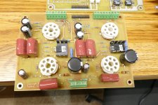
Bias of all six vacuum tube stages was generated with DAC outputs and opamp level shifters, no motorized pots needed. That stuff worked good, and I would have no issue with starting from that point with a Teensy or even a PIC chip.
I found the actual circuit boards that were in the Circuit Cellar amp. They were tossed in a box full of miscellaneous circuit boards that were in my lab in Florida during a "we have 3 weeks to get out of a house we lived in for 37 years" moment.
The contest had a grand prize for "best of show" and several category prizes including "best use of SMPS resources" which drew a much narrower field of entries. My entry won that prize. I believe that those chips came out in late 2006 and the contest ran for several months in mid 2007. The dates on the files in that directory run from June through October of 2007. The magazine article was written in August of 2008 at the request of Circuit Cellar and revised in December of 2008 for publication in the Oct 2009 issue.
Bias of all six vacuum tube stages was generated with DAC outputs and opamp level shifters, no motorized pots needed. That stuff worked good, and I would have no issue with starting from that point with a Teensy or even a PIC chip.
I found the actual circuit boards that were in the Circuit Cellar amp. They were tossed in a box full of miscellaneous circuit boards that were in my lab in Florida during a "we have 3 weeks to get out of a house we lived in for 37 years" moment.
Attachments
I only suggested motorised pots as a method of leaving classic tube amplifiers as original as possible, the additions could be disabled and the amp would work as it did when it left the factory. Basically the auto bias could be activated if new tubes were fitted or rebiasing was required, motor turns pot instead of screwdriver. BTW I used a dsPIC in a 50kW PWM power supply, silicon carbide FET's 400 volts out @ 125A. A huge dummy load was required!Bias of all six vacuum tube stages was generated with DAC outputs and opamp level shifters, no motorized pots needed.
dsPIC33FJ64GS610, 6 x PMW channels used @ 50kHz.
Last edited:
What is controlled by the Teensy?A Teensy controlled guitar amp.......I'm working on that one NOW!
Years ago on another forum we did a system to switch the load of some stages (EG first stage plate from 220k to 100k, cathode from 1k8 to 2k7, etc...), but never did a full pcb. Is it something similar to what you are working on?
The actual Teensy control stuff is not yet completely defined yet, since the stuff being controlled is still being investigated. I will likely include the usual 12AX7 circuits with selectable parts or other means of changing the voicing, but I am also working on a couple ideas that haven't been seen yet, and I'm not afraid to mix silicon and vacuum tubes where it does something useful.
I envision at least two complete preamp paths, one following the usual FMV (Fender, Marshall, Vox) circuitry and another made from totally unique circuitry that I'm working on.....hint. no 12AX7's. Part of the microprocessor control stuff will be the ability to swap individual gain stages in and out of each path.
I envision at least two complete preamp paths, one following the usual FMV (Fender, Marshall, Vox) circuitry and another made from totally unique circuitry that I'm working on.....hint. no 12AX7's. Part of the microprocessor control stuff will be the ability to swap individual gain stages in and out of each path.
Quote Tubelab "I´m not afraid to mix silicon and vacuum tubes where it does something useful."
I´m all for it.. Having done nearly 40 yrs in motive power design, PFC (power factor control) in trams/railway drives, enormous power advantages can be acheived even for Tube amps. However, there are many caveats to grasp, plus the knowledge bump.
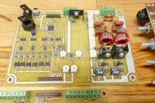
For tube amps the subject of microproc protection can be easily integrated with most power controller ic´s into a power down functions, low mains watchdogs, bias drift etc; and reduced B+, lower Iquies, for easy listening. Plus EBus possibility, all adding to longer tube life. The power amp chassis in pic 2x 250W (8x KT90) though complex (sim to under an old Tekt mainframe) uses analog watchdogs with basic protection coupled to B+ shut down. The PFC can supply 450V at 2A with only 4V variation from full load to quies with no compromises, and this is where care/protection is required. A timed start up and fault protection with silicon can easily be interfaced with other features (which create the complexity). Many possibilities exist.
One can have all the HiFi tube sound without any detriments of silicon influence ! I´m getting on in years but, Go for it.
In the top corner of the pic is a previous generation Tek2445A. Probably one of the best family of analog scopes made in the 1980´s.
Bench baron
I´m all for it.. Having done nearly 40 yrs in motive power design, PFC (power factor control) in trams/railway drives, enormous power advantages can be acheived even for Tube amps. However, there are many caveats to grasp, plus the knowledge bump.
For tube amps the subject of microproc protection can be easily integrated with most power controller ic´s into a power down functions, low mains watchdogs, bias drift etc; and reduced B+, lower Iquies, for easy listening. Plus EBus possibility, all adding to longer tube life. The power amp chassis in pic 2x 250W (8x KT90) though complex (sim to under an old Tekt mainframe) uses analog watchdogs with basic protection coupled to B+ shut down. The PFC can supply 450V at 2A with only 4V variation from full load to quies with no compromises, and this is where care/protection is required. A timed start up and fault protection with silicon can easily be interfaced with other features (which create the complexity). Many possibilities exist.
One can have all the HiFi tube sound without any detriments of silicon influence ! I´m getting on in years but, Go for it.
In the top corner of the pic is a previous generation Tek2445A. Probably one of the best family of analog scopes made in the 1980´s.
Bench baron
Attachments
![IMG_1661[1].JPG](/community/data/attachments/1185/1185382-dc25da827f3ba30170b7184c83d1adaf.jpg?hash=3CXagn87ow)
Having built a few tube testers I found electrical noise had to be kept at a minimum while taking measurements especially with small low powered triodes.
Maybe following design could describe, as a programmable capacitor multiplier.
Referring to the top schematic diagram current source L1 charges C1 to the required voltage, FET M2 functions as a source follower driving the output load R2.
Obviously the constant current source will charge C1 in a linear manner.
This basic circuit was used in my latest tube tester for B+, screen, heater/filament and bias, with the bias default off with max negative bias.
All voltages are updated a few times a second and prior to reading the tube under test.
The fact that nothing is happening when the read takes place keeps the noise down.
I disabled the 6.3V heater update drive and the heater voltage was still in specification after many minutes.
I used the fact that most optocouplers actually generate a current from their base collector junction in much the same way a solar panel works. The voltage is clamped at one PN junction so the maximum voltage is about 600mV so two optocouplers were required to forward a bipolar transistor.
I found the KSC5027 a high reliability bipolar transistor had very good "off" leakage and was quite suitable for the task
In the tube tester the soft ramp up and down can often be used to ones advantage.
Although the circuit was intended for a constant load it performs rather well driving other loads.
Why did I use it for the heater supply? It was easy. I was intending to have an extra few volts available for heater the pull up current source so the heater supply could work as a low dropout regulator, never got around to it.
The LED current verses the generated current out of the optocoupler in the photovoltaic mode is approximately ratiometric
A microcontroller constantly monitors the voltages and makes adjustments if not at the set value.
Photovoltaic optically coupled MOSFET drive IC's are available, I'm uncertain if they would be any better having to charge up the gate capacitance, also one would need to consider their "off" leakage. standard optocouplers are quite fast in this mode.
Attachments
I reckon any improved awareness of faults in a valve amp is well worthwhile. As indicated, the changing valve manufacture scene has meant that 'modern' tubes present a higher risk of various faults than has been experienced in the past, and vintage amps are not getting younger and age will continue to show up more failed parts, whereas quality control and performance of most (non-valve) electronic parts and pcbs etc have benefited from being more 'modern'.
I would caution that even the examples of faults in this thread indicate a general lack of awareness of making valve amps more 'bullet proof' by remedial addition of parts to mitigate well known and reasonably common faults - certainly common enough to be found in many posts/threads over many forums. I suggest that any micro-controller based effort should be based on a reasoned description of each target fault type, and an assessment of mitigating hardware that would act as the 'first responder' to such a target fault, and that such awareness would then result in the conditions that aren't being met by remedial hardware and hence better define the monitoring conditions and programmable outcomes that could accrue. The risk I see is that some may put a lot of well-intentioned (but perhaps naive) effort into a micro-based solution, and others may use or copy the solution thinking it is 'THE' solution to a fault, without having a pre-cursor assessment available and reviewable for practicality/validity.
The use of some remedial parts are becoming more well-known, such as adding series ss diodes to rectifier valve anodes - and spurred on by forum posts on failed modern rectifier valves, but I'd guess that few have retrofitted such parts. Similarly, few would have assessed their amp's mains fuse value for performance, or added additional secondary-side fusing as back-up protection to minimise collateral damage. Another less well-appreciated remedial part is the use of MOVs across output transformer primary windings, given that many believe 1-3kV catch diodes as used from early 1970's in well known commercial guitar amps must be the most appropriate solution.
It may also be worthwhile having at least two uP paths that are as simple as possible, with perhaps one path based on easily purchased parts/programmers/pcbs/relays etc and access to code for just one or a small number of basic functions, and perhaps another path for diyers who can spin up or send off a gerber to get a pcb made, and can do very simple programming changes to already vetted software, as a form of customising to a particular amp they have.
I could see a microprocessor (uP) in a complex S.S. design, but it looks like overkill for a tube amp, although it could work there. Part of the charm of a tube amp is its simplicity, and there's really not that much for a uP to do there. I can't see overcomplicating a tube amp with something like that. A uP in a tube amp is just a solution looking for a problem to solve.
Come back when you have a bad back and you want a bluetooth remote instead of a scratchy tone control attached to the rig. 😆
In that case, if mobility due to disability is a problem, then a remote control would make perfect sense. For someone in good physical health, it wouldn't hurt to get off your musty dusty oldie moldy goldie and make any needed adjustments. If tone adjustments are needed by way of bass, treble or EQ control, then using a remote while sitting in the listening position would make sense, since tonality can change with position in the listening room.
- Home
- Amplifiers
- Tubes / Valves
- Microcontrollers in tube amplifiers