Yes. You should move the ground point away from the first capacitor.
Transformers are most susceptible to noise pickup and radiation from the exposed winding side so their orientation is good. Shielding may help but it's difficult to do well.
I would try moving the ground point first. Then look at the input area. The low level signal routing needs to be away from the power supply.
Is it possible to ask the manufacturer/designer? Since it is not DIY, the presumption is that many units of such layout/construction are successful. If the amp is new to you, perhaps some builder built it differently than the "usual" ways? Just asking. trobbins is always rock-solid, it's just that perhaps everyone reading would likely approach different things to figure out what's happening. Just one free opinion, but my sense is that there are fundamental (routing/layout) things to fix before considering application of an external choke with nice wire. I know you said it's 120, but I'm seeing a lot of inductively coupled stuff in there, shielded or not, large current next to small signal, etc. I think you need to disconnect things, jumper things, measure, etc. to find the causality of the inputs-shorted hum. FWIW. Are there other support forums for your specific product, maybe, that you might inquire on?
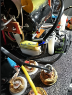
The 'audio ground take off' is the black wire running just above the yellow cap in the photo. The other end of that wire is connected to a 10 ohm resistor and capacitor in parallel, then the other side of those are connected to the ground (earth) of the socket where the power cord plugs into. I will work on a schematic of the rest of the amp. Did you see the schematic that I posted initially, of just the power supply?
The black wire in the photo below, starting just to the right of the 'audio ground' is the 'take off', it connects to the node in the previous photo, at the negative terminal of the first filter caps.
The black wire in the photo below, starting just to the right of the 'audio ground' is the 'take off', it connects to the node in the previous photo, at the negative terminal of the first filter caps.
Attachments
Yes, it is possible that it was built by someone new, or possibly someone very busy. When I first received the amp I contacted the company that built it and he told me that I was hearing 'power supply ripple', at first I could not hear it from the listening position, but has since become louder, or my room has become quieter, so now I can hear it from the listening position. I realize that I have sensitive speakers (98dB), but I still don't think that I should be hearing power supply ripple from the listening position, as I get closer to the speakers the hum gets louder. I do need to schedule a call with the manufacturer. It would be great if it could be resolved without adding the LC filter. It looks like I am maybe getting a bit ahead of myself. I am not planning to make any modifications until I can determine for sure what is causing the hum. However, the model of the power supply in PSUD2 does show about 0.5 V of ripple on the B+, and I believe that the output transformers are 1:25, which would translate to 20mV on the output side of the transformers, fairly certain that 20mV is audible.Is it possible to ask the manufacturer/designer? Since it is not DIY, the presumption is that many units of such layout/construction are successful. If the amp is new to you, perhaps some builder built it differently than the "usual" ways? Just asking. trobbins is always rock-solid, it's just that perhaps everyone reading would likely approach different things to figure out what's happening. Just one free opinion, but my sense is that there are fundamental (routing/layout) things to fix before considering application of an external choke with nice wire. I know you said it's 120, but I'm seeing a lot of inductively coupled stuff in there, shielded or not, large current next to small signal, etc. I think you need to disconnect things, jumper things, measure, etc. to find the causality of the inputs-shorted hum. FWIW. Are there other support forums for your specific product, maybe, that you might inquire on?
Yes, there are forums on the manufacturer's website, and I have asked for some advice on those forums as well. I just have been cautious as I don't want to do or say anything that might 'sound negative about the designer'.

I would move the ground point and then get some electrolytic capacitors and alligator clip them to where the power to the transformers take off. This will tell you if there is insufficient filtering or if the hum is originating from other sources.
Different names mean different things to different people, so well worth trying to clarify imho. Your first schematic does not show the actual node connection layout of the 0V bus, only a simplified schematic representation. The 'audio ground take off' is also described as the link between mains/chassis earth and the 0V bus, even though that link has an RC network in it.
I doubt that the chassis-to-0V link is a significant issue to your hum concern, but like all things, the devil may be in the detail and suggesting mods or tests is best done with a good appreciation of exactly what you have.
Your presumption that 0.5V of B+ ripple translates to 20mV of ripple across the speaker has a few issues. For starters it requires the anode end of the output transformer primary winding to be grounded, which it wasn't for your test with the output stage tube removed. My initial view is that primary winding does have a path to chassis through parasitic capacitance, and that path may be substantial enough to cause what you are hearing. The other mechanism is field coupling from the power transformer to the output transformer, which is typically managed by the manufacturer rotating or orienting those two transformers in a manner to minimises hum coupling. It could also be a combination, not just one or other, and could be something else entirely.
The parasitic capacitance path option should be influenced by temporarily adding more first filter capacitance (or other remedial RC or LC filtering on the way to the output transformer), as that would reduce B+ ripple and hence coupling of ripple to the speaker from that path option.
Minimising hum when it is at a level that is quite low can be onerous - but as you and others have found, using modern day speakers in good listening rooms with low noise source material, is a modern day inconvenience.
You are absolutely right that sometimes I need to clarify things better, and I really do appreciate all the help and clarifications.
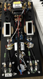
Where is the power transformer located? I think I can see input jacks next to the AC power jack. The layout does not appear to be ideal.
Also, would have been better to use more filter capacitance rather than the film bypass capacitors. You can probably squeeze in more electrolytic capacitors if you removed the film capacitors.
Also, would have been better to use more filter capacitance rather than the film bypass capacitors. You can probably squeeze in more electrolytic capacitors if you removed the film capacitors.
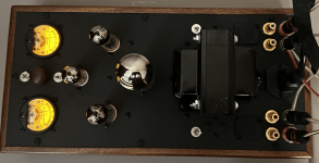
The power transformer is located near the back of the amp. I have attached a couple of photos for clarification.
I have read that the reason more input capacitance was not used was because it would be bad for many rectifier tubes.
I also need to clarify that I have the capacitance of some of the tubes labelled incorrectly. I checked with the manufacturer and they should be as on this scheme.
I have read that the reason more input capacitance was not used was because it would be bad for many rectifier tubes.
I also need to clarify that I have the capacitance of some of the tubes labelled incorrectly. I checked with the manufacturer and they should be as on this scheme.
Attachments
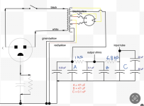
The first capacitor, A, should be limited to the value imposed by the rectifier tube, but the second capacitor, B, after the 1k ohm resistor can be increased. Leave A alone, and try increasing B.
I would still try moving the ground point, as well.
The location of the input jacks, next to the AC power and power transformer is not a good arrangement. It would have been better if they were located at the other end of the amplifier. I guess some people wouldn't like the look, but it wouldn't bother me.
Here is a good writeup on amplifier layout and wiring for low noise: https://hifisonix.com/wp-content/uploads/2019/02/Ground-Loops.pdf
Likely better to use ss rectifier if that is convenient as that sidesteps the risk to the rectifier valve (you can do a PSUD2 assessment of rectifier peak current and compare to datasheet, but it requires measurement of power transformer winding resistances, and some learning curve).Would it be safe to try them, one first, then a second, in parallel with the existing 1st filter caps using alligator clips to test if it makes a difference.
I would use the solid state rectifier to avoid possible damage to the valves.
For better fault protection going forward, you should imho check out the 'yellow sheet mod' and retrofit ss diodes before the valve rectifier diode anodes.
Don't forget about safety, and hardwire a bleed resistor across each cap. Try and use a repeatable 'measurement' of hum level to compare changes against - perhaps try and use some form of meter/reading instead of your ears.
I added 66uF of capacitance after the 1k resistor using alligator clips. I did not hear any difference in the hum from the speakers. Unfortunately the only measuring device I have is an app on my iPhone. It is possible that it is not sensitive enough to measure any difference. According to PSUD2 the B+ ripple should have went down from 234mV to 99mV.
I think my next step will be to discuss this with the builder/manufacturer and see if they can do anything to help.
I think my next step will be to discuss this with the builder/manufacturer and see if they can do anything to help.
I would try shorting the inputs at the voltage amplifier tube to see if that changes the hum. The input plugs near the AC and power transformer are susceptible to hum pickup. Follow the input cable from the jacks to the front end and jumper the signal to ground there.
Would this be relevant given that the hum is present with no audio tubes installed? I have also had the RCA inputs shorted using shorting plugs.
Forgive me, I just want to make sure that this would be something different to try?
Forgive me, I just want to make sure that this would be something different to try?
Cabling can act as antennae and pick up hum. I'm thinking that shorting the input at the tube hopefully removes the effects of the input cabling and the proximity of the input jacks to the AC and power transformer.
I follow the scientific method when problem solving, so I'm trying to think of all things that may be having an effect and then performing experiments to test the hypotheses. That will help narrow the field of things to explore. You can spend too much time theorizing and not enough time testing.
I follow the scientific method when problem solving, so I'm trying to think of all things that may be having an effect and then performing experiments to test the hypotheses. That will help narrow the field of things to explore. You can spend too much time theorizing and not enough time testing.
Did you move the ground point? Taking the ground from the first filter capacitor's negative terminal is really not a good idea. You can use PSUD2 and look at the ripple current through the first capacitor and compare it to the ripple current through subsequent filter capacitors.
I have not moved the audio ground take off wire yet. I need to get a soldering iron for that. Any that you recommend?
I would recommend a good temperature controlled iron. I like the Hakko brand, for example the FX-888D, but they are not the cheapest. If you intend to continue with DIY electronics, then it would be a good investment. There are others, though, which I'm sure you can find info on through a search.
- Home
- Amplifiers
- Power Supplies
- Add LC Filter / Choke