I try to calculate the Z of CCS low mu E180f triode for a phono preamp with LCR eq to match the LCR haismoto 600ohm need to be precise in z out:
Zout = Rp / (1 + μ * gm * (Rp + Rk))
Rp ( triode ) = 2700 ohm
μ = 50
Rk ( her207 diode cathode ) = 5 ohm ( maybe less )
Zout = 2700Ω / (1 + 50 * 4.4 mA/V * (2700Ω + 5Ω)) ≈ 11.54Ω
Who can confirm the Z out
Any idea, I'm not familiar with these formulas found on the internet.
other option to match without loose gain transformer 2700:600 4.5:1 loose 4.5 times the gain.

The best way to feed a 600 LCR is to feed it through a Zout+R=600ohm and terminate the network with highZ. This gives a Zin of 1200ohm. R can then be matched to compensate for other Zout values. In the link below you can find my thread from intactaudio on the subject. Later in the thread there are lot of LTSpice simulations and schematics from me and Dave Slagle.
intactaudioforum
intactaudioforum
Here some info maybe interesting
And real tests
https://www.diyaudio.com/community/threads/lcr-phono-stage.370081/
And real tests
https://www.diyaudio.com/community/threads/lcr-phono-stage.370081/
well the question is how calculate the Z in CCS low mu with E180f as triode
Zout = Rp / (1 + μ * gm * (Rp + Rk))
Rp ( triode ) = 2700 ohm
μ = 50
Rk ( her207 diode cathode ) = 5 ohm ( maybe less )
Zout = 2700Ω / (1 + 50 * 4.4 mA/V * (2700Ω + 5Ω)) ≈ 11.54Ω Is correct ??
I need to know the Z to adjust to 600ohm with Resistor before LCR,

Zout = Rp / (1 + μ * gm * (Rp + Rk))
Rp ( triode ) = 2700 ohm
μ = 50
Rk ( her207 diode cathode ) = 5 ohm ( maybe less )
Zout = 2700Ω / (1 + 50 * 4.4 mA/V * (2700Ω + 5Ω)) ≈ 11.54Ω Is correct ??
I need to know the Z to adjust to 600ohm with Resistor before LCR,
"Zout = Rp / (1 + μ * gm * (Rp + Rk))"
Where did you find this formula?
It shows nothing of anode load parameters.
If you use simple grounded cathode stage, the output impedance is (un-bypassed cathode resistor Rk, triode rp, Ra anode load) from the anode:
Zo = (rp + [mu +1]*Rk ) || Ra
If you use CCS, the CCS impedance is orders of magnitude greater than tube's rp, so from anode the output impedance is almost rp.
If you use CCS (mostly with FETs), and the output is the "Low Z", it's rather mu-follower, so output impedance depends a lot of semiconductor gfs (it's like tube gm).
Are you know this blog?
https://www.bartola.co.uk/valves/2018/04/28/hybrid-mu-follower-output-impedance/
Hi Euro, the formula is from GPT but I remember that a CCS with 10m45s or DN2540 normally low mu have a Z more or less Rp/3 or Rp/4 never Rp/10, is why I ask here. In the link have you sent Ale Moglia explain clearly thanks.
GPT 0 ALE 1
GPT 0 ALE 1
BTW if you want to load LCR EQ module, there is two method:
1.) driving it with LCR (estimated) own impedance (for example 600R) and loading with large resistance (as @revintage suggested);
2.) loading it with 600R and driving with undetermined (not 600R, but not larger than few kOhm) impedance.
The LCR modules average loss is -about- 20dB (1kHz).
1.) driving it with LCR (estimated) own impedance (for example 600R) and loading with large resistance (as @revintage suggested);
2.) loading it with 600R and driving with undetermined (not 600R, but not larger than few kOhm) impedance.
The LCR modules average loss is -about- 20dB (1kHz).
Mosfet CCS? Then as drawn - cascade follower - the tube will have little impact on Z out.well the question is how calculate the Z in CCS low mu with E180f as triode
Euro21,2.) loading it with 600R and driving with undetermined (not 600R, but not larger than few kOhm) impedance.
Absolutely correct. On the downside is that the LCR network must be driven by an very lowZ source, if the signal loss is to be kept to a minimum. Ie a Zout of 1.8k will give a loss of 12dB(added to the 20dB loss in the network). Consequently a driver Zout of 600ohm will give a 6dB signal loss.
This means a E180F should be used with a CCS follower with enough current to drive the network. In this case the Zout is not critical.
Last edited:
In this case with E180f CCS low z has more or less a Z = 600 ohm seem ok for hashimoto lcr, that was my first thinking.
Be sure, that before LCR module -enough large- capacitor exist. CCS output is on large DC voltage.
Good point. I never calculated the response of LCR passive RIAA correction networks, but the first pole of passive RC RIAA correction networks is often very sensitive to the reactance of the coupling capacitor.
In the link I attached there are lot of tests made non deskGood point. I never calculated the response of LCR passive RIAA correction networks
I see you use coupling capacitors in post #8 of the thread you linked to, https://www.diyaudio.com/community/threads/lcr-phono-stage.370081/post-6629118 , but what was their value and how did they affect the response below 200 Hz?
I started from 47 uF ( as storic Shishido) and the final was 66 uF ( 2x 33uF poliprop caps)but what was their value
Seems to the right value for a good response on low freq
I have tested other tube as CF
6H30
6H6
ECC99
Good results also with little differences
I also tested with Tango Eq and Sowter coils
The results are comparable
Need to select the eq caps
Walter
Good to start with 47u as it should give -0.25dB at 20Hz, with 66u -0.15dB. Selecting RIAA caps is critical as the coils have value spread, anyway with Lundahl and Tango.I started from 47 uF ( as storic Shishido) and the final was 66 uF ( 2x 33uF poliprop caps)
coils have value spread
I have used three types: Tango, Sowter and ELtra ( customa made in Italy)
The last two are similar to Tango and the results are also fine.
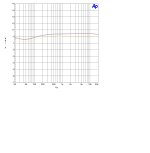
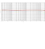
In attach the respone of LCR network only
Zs=600 ohm
Zload= 100k (red), 47k (blue), 10 k (yellow)
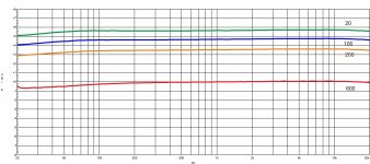
Then the response with diffrent Zsource and Zload=600 ohm
little bit better and different level
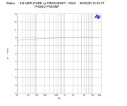
Then the response of Tango network terminated with 600 ohm
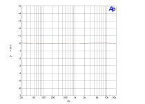
Then the resppnse of all circuit with the load of LCR with 600 ohm anf in parallel a trimmer to fix the best response, it is only a test.
The trimming of load compensate the little differences on coils and other components mainly in th e low freq.
In the final test the trimme was no used and the respnse was also good.
Last respone
In every case the LCr MUST be terminated with 600 ohm.
As the Tango data sheet says
Attachments
- Home
- Amplifiers
- Tubes / Valves
- CCS low mu