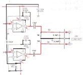
OK, back off then. And regarding c324 and c323, the capacitors on the output AOP rail : 470uF 16v ! is a polymer oscon possible ? at least 20v on the other hand ! and is a greater capacity could be better (in this case a panasonic fr 1000uF) ?
Bigger is not always better when it comes to adding caps to rails. I would not start altering PSU cap values without a very good reason to do so 🙂
Will a polymer Oscon work OK, almost certainly yes is the answer. Would I fit a 1000uF instead of 470uF, no because it achieves nothing on a regulator output beyond altering rail sequencing and rise and fall times.
Will a polymer Oscon work OK, almost certainly yes is the answer. Would I fit a 1000uF instead of 470uF, no because it achieves nothing on a regulator output beyond altering rail sequencing and rise and fall times.
Regarding ESR and ripple current, what are the rules to follow in the use of polymer or chemical capacitors?
which technologies and characteristics to favor depending on the section of the diagram: digital/analogue, presence of regulators or absence...
Of course never in the signal path
which technologies and characteristics to favor depending on the section of the diagram: digital/analogue, presence of regulators or absence...
Of course never in the signal path
For PSU use you need to look at both ripple rating and the way it is measured and the way the rated lifetime of the cap is measured and make a balanced judgement depending on the application. Higher ripple rating is usually an advantage in high ripple applications like reservoir caps but it means little for decoupling on regulated rails where there is no ripple to begin with.
I haven't studied polymer caps to see what any limitations might be.
The thing with any cap replacement is to identify what problem you are trying to solve (to lower ripple for example could be one problem or improving longevity in SMPS applications would be another).
There are no hard and fast rules. Increasing reservoir cap value reduces ripple at the expense of higher peak charging currents which in turn can tend to push a mains transformer into saturation making it noisy and running hotter than it should.
Hi,
The restoration is complete, but...
When I plug in the cable (switch off) the transformer heats up quickly and hums slightly.
On, the display no longer works, the music is inaudible.
There is no continuity on the RCA. OK !
Modifications :
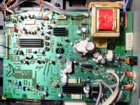
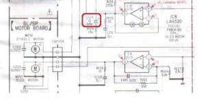
the output stage + muting are visible on the jpeg.
I placed a filter on the sector, the ground (floating) is connected to earth.
Soon I will dismantle the facade.
Can you guide me to correct my error please ?
The restoration is complete, but...
When I plug in the cable (switch off) the transformer heats up quickly and hums slightly.
On, the display no longer works, the music is inaudible.
There is no continuity on the RCA. OK !
Modifications :
the output stage + muting are visible on the jpeg.
I placed a filter on the sector, the ground (floating) is connected to earth.
Soon I will dismantle the facade.
Can you guide me to correct my error please ?
Attachments
Can you guide me to correct my error please ?
You will have to back track over all the work and modifications you have done. The transformer heating up quickly and humming points to short or near short on a supply line. DO NOT let the transformer run for to long like that because if there is an embedded thermal fuse it WILL fail when hot enough and then the transformer is scrap.
Nothing you have done in the output and muting could cause this unless you have introduced a short somehow. Make sure any PSU caps are the correct way around. Feel them and make sure they are all cold.
Hello, I only found c124 mounted upside down, see attachment.
I expected to find a capacitor paste short circuiting with a neighboring track, but today's examination showed nothing.
In the analog stage, I shielded the aerial connections, next time I will remove all this tow.
When I plugged it in to test, the audio is still bad.
Without having to wait long, the transformer always heats up quickly.
Would a lesson be not to weld until 2 a.m.?
Attachments
If that cap really is in series with a 33k as shown then it could not draw any significant current because the 33k is the limiting factor.
You've done a lot of mods and that has caused problems. You have to go back to basics and check things like all the rail voltage. You mentioned that even the display doesn't work now... so something bad has happened with all those mods 🙁
You've done a lot of mods and that has caused problems. You have to go back to basics and check things like all the rail voltage. You mentioned that even the display doesn't work now... so something bad has happened with all those mods 🙁
+1You've done a lot of mods and that has caused problems. You have to go back to basics and check things like all the rail voltage. You mentioned that even the display doesn't work now... so something bad has happened with all those mods 🙁
+2

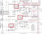
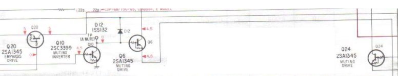
C138 is shown correctly with the + (plus) terminal grounded. That is correct. The - (negative) side should not have direct continuit to ground. If it does then you have a short on that negative 9 volt rail.
I will test the capacitor first. The short circuit may have come from him. Otherwise I'll open my eyes better. Tomorrow
after a new search: nothing. Otherwise that the new diodes, measured empty, diode function on the metrix indicates 0.36V against 0.57 for the old ones. The new ones show around 330 ohms when I test the continuity at no load, the old ones say nothing. The new ones are vishay SB1H100-E3/54.
Could a component be defective? Should I test them one by one?
THANKS
https://docs.rs-online.com/c376/0900766b8100a450.pdf
Could a component be defective? Should I test them one by one?
THANKS
https://docs.rs-online.com/c376/0900766b8100a450.pdf
The Vishay parts are Schottky diodes and will have a low forward voltage compared to general purpose silicon types.
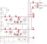
I would begin by checking if all the CP's (the circuit protectors are OK) on the basis that a short on a rail after those should blow them. If they are all OK then identify all the rail points before the CP's and quickly (before the transformer heats up) measure them all. Do it quickly though to stop the thermal fuse blowing. See if any rail is very low or missing.
There are 6 rails in total to measure that I can see.
It could be anything because it is something related to the work you have done. It might even be a solder blob you haven't spotted.Could a component be defective? Should I test them one by one?
I would begin by checking if all the CP's (the circuit protectors are OK) on the basis that a short on a rail after those should blow them. If they are all OK then identify all the rail points before the CP's and quickly (before the transformer heats up) measure them all. Do it quickly though to stop the thermal fuse blowing. See if any rail is very low or missing.
There are 6 rails in total to measure that I can see.
- Home
- Source & Line
- Digital Source
- about upgrade Yamaha CDX630e clone Sony CDP750