Yes, there are an infinite number of ways to distort a signal, but the original signal is only one.
EricdeBest,
It seems like you should easily be able to use the push pull output transformer. I like the idea of no air gap, more inductance, and potentially less leakage inductance primary to secondary.
I wish I had time and effort to build an amplifier like you are proposing.
The simplest one would use either a pair of pentodes or a pair of beam power tubes.
They should be well matched, and need to have individual self bias resistors in order to make the currents match quite easily.
The one that amplifies signal would have a bypass capacitor across its self bias resistor, to keep its gain, and lowest plate impedance, rp.
That plate drives one end of the primary.
The one that is used to pull quiescent current on the other end of the secondary would Not have a bypass cap across its self bias resistor;
that would greatly increase its plate resistance, rp, making it a better constant current source (in this case a better constant current sink).
The output tube that is driven could be in native pentode or native beam power mode.
Or it could be Triode wired: Trading off output power; for lower distortion and higher damping factor.
The constant current tube should be in native pentode mode, or native beam power mode.
The driver only needs to be single ended, no phase inverter needed.
Seems pretty simple and straightforward to me.
Thanks 6A3ErikdeBest,
You mentioned an amplifier that can do both single ended, and push pull. Lots of examples for that.
But you said: "this allows the SE sonic signature using PP OPTs"
Other than preventing saturation in a single ended amplifier, is there Any other characteristic that an air gap gives to the 'sound' of single ended?
Some push pull amplifiers use an Air Gapped push pull output transformer.
Why would they do that?
For a different sound?
The French built 2 single ended amplifiers with air gaped output transformers, and then drove the inputs with opposite phase, and then switched the output transformer secondaries in opposite connection (in parallel). That properly combines the two phases at the outputs.
I tried that once myself.
I think we are not finished with the science, and we are not finished with the perceived sound of the many different topologies of vacuum tube amplifiers.
That is why it is so important for you and others to keep developing these ideas.
Happy designing, building, and listening!
It is a Mean thing to say that Karl Friedrich Gauss was an Average man, who was Centered on his Gaussian Curve.
You know that in a well-balanced PP amp, the even harmonics are cancelled in the OPT. If the drive signal is reduced to one of the output tubes, or completely cut, this will not produce any output anymore, so also no even harmonics to cancel (or uneven harmonics to add) to the fully driven side (as suggested, this can be done with a potentiometer as grid leak for the output tube). That is what I mean with the SE sonic signature using the PP OPTs.
I did not think much about the influence of the air gap itself, but I know there is a lot of discussion around it. I was testing some 50/60Hz toroidals as output transformers, their performance deteriorated considerably with DC imbalance (was expected). So I like what Lundahl does with the C core transformers: even in PP ones they put a little gap, if I were to order a PP OPT for a paif of EL84 I would ask for a gap for at least 5mA disbalance, as I can happily live with the idea of a small reduction in primary inductance.
Erik
I think it was Nelson Pass that said that 1/3 of people like even harmonics, 1/3 like uneven, and 1/3 no distortion at all. Maybe it also depends on the music style? I believe that complex music (orchests, choirs) can profit from low distortion, but if I listen to some cat power that I heard first some 25 years ago, some "mellowness" around that nostalgia may be beneficial - dial a pot to get it 🙂Yes, there are an infinite number of ways to distort a signal, but the original signal is only one.
"1/3 like uneven" I'm not agree with this value, maybe maximum 1/10
Have you tried this? I doubt it is that simple to modify and test. If a tube is not properly ordered, the transformer quickly gets saturated........You know that in a well-balanced PP amp, the even harmonics are cancelled in the OPT. If the drive signal is reduced to one of the output tubes, or completely cut, this will not produce any output anymore, so also no even harmonics to cancel (or uneven harmonics to add) to the fully driven side (as suggested, this can be done with a potentiometer as grid leak for the output tube). That is what I mean with the SE sonic signature using the PP OPTs.
........
This is indeed the simplest solution, different variations and their implications are shown and explained at the website I linked to from Ciufolli.EricdeBest,
It seems like you should easily be able to use the push pull output transformer. I like the idea of no air gap, more inductance, and potentially less leakage inductance primary to secondary.
I wish I had time and effort to build an amplifier like you are proposing.
The simplest one would use either a pair of pentodes or a pair of beam power tubes.
They should be well matched, and need to have individual self bias resistors in order to make the currents match quite easily.
The one that amplifies signal would have a bypass capacitor across its self bias resistor, to keep its gain, and lowest plate impedance, rp.
That plate drives one end of the primary.
The one that is used to pull quiescent current on the other end of the secondary would Not have a bypass cap across its self bias resistor;
that would greatly increase its plate resistance, rp, making it a better constant current source (in this case a better constant current sink).
The output tube that is driven could be in native pentode or native beam power mode.
Or it could be Triode wired: Trading off output power; for lower distortion and higher damping factor.
The constant current tube should be in native pentode mode, or native beam power mode.
The driver only needs to be single ended, no phase inverter needed.
Seems pretty simple and straightforward to me.
Assume I want an amplifier one can call "HiFi'', so not a distortion machine with eg saturated OPTs etc. A bit of challenge is that in the PP setting it would be nice if both output tubes have low plate impedance, triodes come to mind. But in the SE setting it is indeed better to have as high as possible impedance, so pentodes (with unbypassed cathodes). Being able to change (continuously) between these two extremes for one leg of the amp only, maintaining the same overall gain, makes it a bit more complex. First idea is to indeed use NFB, which reduces the plate impedance of pentodes. Turning the potentiometers towards SE, I want to at the same time reduce the amount of audio signal as well as feedback to one leg of the amplifier, so that the pentode in this leg contributes less to the audio amplification and with reduced feedback will start acting more and more as a CCS only. At the extreme of the potentiometer, there will be no audio signal and no FB at it, so a pure CCS.
The final idea is to have this as a power amplifier, but I may start with a headphone amplifier where the required power levels are much less.
I haven't done the research, but the idea is probably that tastes differ - what a surprise 🙂"1/3 like uneven" I'm not agree with this value, maybe maximum 1/10
Have you tried this? I doubt it is that simple to modify and test. If a tube is not properly ordered, the transformer quickly gets saturated.
Indeed, the OPT can get saturated, MerlinB warned about this in his first reply. I am trying to avoid it by keeping the DC conditions throughout the continuous change between PP to SE, varying only the AC conditions under which the tubes play.
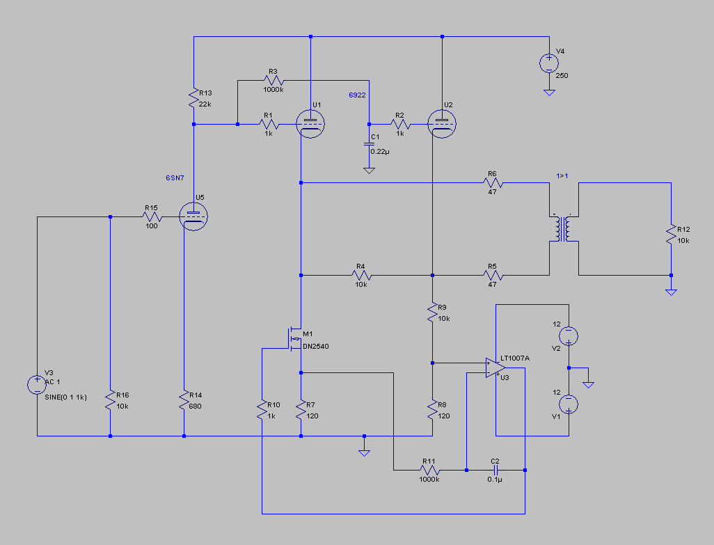
Eventually I went for an UNSET @Tubelab_com concept as testbed for this amplifier. Contrary to George, I am currently happy with 0.5W of power 🙂, as a possible first application will be a headphone amp.
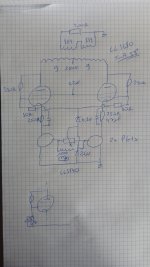
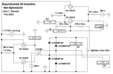
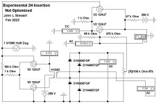
The OPT is a LL1680, gapped for 5mA, ratio is 9+9:1//1+1//1. Currently using a 100R load resistor, should actually be more like 150R, which is the impedance of my HD590 headphone. The input transformer is a LL1540 1:1 driven from my test soundcard. The tubes are 6E5P. The 250R resistors were chosen to get around 30mA through each tube.
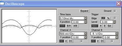
Currently there is only one pot (100k) in there, the extremes go the PFet gates, the wiper to a bias point. And the concept works: when the wiper is in the middle, total THD is smallest, with 3rd higher than 2nd. Turning to either side the 2nd and 4th starts increasing fast, at certain position the 3rd goes down, overall THD is higher.
At the bottom of the picture you see what I still want to implement: replace one 10k resistor with a potentiometer, with a cap from wiper to ground. This is why I choose the UNSET as it allows to simply change the feedback amount around a single tube, as the "gain" of the tube is set per individual tube with two resistors. With the 10k bypassed, there is no feedback, so pentode, with the 10k non-bypassed, there is feedback. The idea is to eventually couple both pots, in one extreme both tubes get the same signal and feedback is applied (so two triodes in PP), at the other extreme only one tube gets (double) the signal, the other has no feedback and acts as a relatively good CCS.
The OPT is a LL1680, gapped for 5mA, ratio is 9+9:1//1+1//1. Currently using a 100R load resistor, should actually be more like 150R, which is the impedance of my HD590 headphone. The input transformer is a LL1540 1:1 driven from my test soundcard. The tubes are 6E5P. The 250R resistors were chosen to get around 30mA through each tube.
Currently there is only one pot (100k) in there, the extremes go the PFet gates, the wiper to a bias point. And the concept works: when the wiper is in the middle, total THD is smallest, with 3rd higher than 2nd. Turning to either side the 2nd and 4th starts increasing fast, at certain position the 3rd goes down, overall THD is higher.
At the bottom of the picture you see what I still want to implement: replace one 10k resistor with a potentiometer, with a cap from wiper to ground. This is why I choose the UNSET as it allows to simply change the feedback amount around a single tube, as the "gain" of the tube is set per individual tube with two resistors. With the 10k bypassed, there is no feedback, so pentode, with the 10k non-bypassed, there is feedback. The idea is to eventually couple both pots, in one extreme both tubes get the same signal and feedback is applied (so two triodes in PP), at the other extreme only one tube gets (double) the signal, the other has no feedback and acts as a relatively good CCS.
Attachments
As you have found, a cap and pot in series from G1 to ground will change the feedback ratio above a frequency determined by the cap value. The action at DC remains the same.
Operating the control grid at a fixed low impedance DC voltage source while driving the cathode with a mosfet follower or low DCR transformer winding will result in pentode like curves for the tube / mosfet combination. Operating the control grid with a resistive divider from plate to ground will result in triode like curves whose shape can be controlled by the ratio of the feedback resistors.
It is possible to make a tube / mosfet combo with a variable adjustment from pentode to triode operation in this manner. As with their all tube counterparts the pentode mode will have more overall gain than the triode mode in the same circuit.
I have build both push pull and SE amps with this technology and am currently experimenting with some offshoots for a guitar amp that goes past 11. The first real use was a two stage SET amp that had no triodes, hence the name UN-SET. There is also a SET amp that has no tubes, but a very realistic SET sound. My version used high voltage mosfets, 250 volts of B+ and a SE vacuum tube OPT. This one is the FETSET.
The UNSET idea got built in silicon by another forum member in this thread. I built a copy in post #761 which morphed into the first FETSET proto in post #787. I still have a working FETSET amp that makes about 15 WPC. The bigger one with parallel mosfets never worked right and eventually wound up in a box somewhere.
https://www.diyaudio.com/community/threads/schade-common-gate-scg-preamp.380487/page-39

Here is the bones of a circuit I posted here on DIY a year ago. It makes it own odd order harmonics by a separate channel.I can’t remember having seen an amplifier that allows (gradual) transition between PP and SE,
These are added in whatever degree the user would like. Something to think about.
Or not.🙂
Attachments


There was also this thread. https://www.diyaudio.com/community/threads/variable-harmonizer.171047/
Due to space constraints I can't have a separate preamp, so it is source with active crossover straight into power amps. Let's first finish the above one and do some extensive tests with my headphones, to see what I like 🙂
Due to space constraints I can't have a separate preamp, so it is source with active crossover straight into power amps. Let's first finish the above one and do some extensive tests with my headphones, to see what I like 🙂
The circuit does what the title of this thread asks for.
But posted here only as a curiosity.
I did say 'something to think about. Or not'.
So I'll add you to the 'Or not' category.👍
But posted here only as a curiosity.
I did say 'something to think about. Or not'.
So I'll add you to the 'Or not' category.👍
Can you tell me where you posted this originally? I surely missed it, maybe there is more info there or someone that optimized it?
I don't recall anyone trying this or something like it. Looks like it died.
Circuits with a side channel are common. You are probably aware
of expander/compressors. A side channel amplifies the signal that is used
to control the mail channel gain.
Circuits with a side channel are common. You are probably aware
of expander/compressors. A side channel amplifies the signal that is used
to control the mail channel gain.
Spell Check sometimes yields rather comical results. That should be 'main' not 'mail'.to control the mail channel gain.
The signal wouldn't lineup well if one came by snail mail.😀
Hi!I don't recall anyone trying this or something like it. Looks like it died.
Circuits with a side channel are common. You are probably aware
of expander/compressors. A side channel amplifies the signal that is used
to control the mail channel gain.
Actually I don't know much about audio circuits other than HIFI, learned a lot from the classical circuits and Morgan Jones. Besides the GM70 in SE, I mostly build PP stuff because of overall lower distortion, but then reading how nice that 2a3 amp sounds, it makes one curious. In this amp the components stay the same, only distortion profile is changed (and PSRR), how does that work out on the percepties quality?!
I wonder if this idea of switching between SE and PP can apply to the preamp side. I saw a "half dead" circuit by JC Morrison in his webpage, inspired by the Mullard phase inverter circuit, that one side of the cathode followers has no AC signal but allows an ungapped output transformer to be used in direct coupling on the two sides of the primary. What if we inject some out of phase signal into the "dead half" and will that create more of a PP (or somewhat dead) characteristic?
I will check the link, always nice seeing the work by JC.
Yesterday I did some further tests, replacing one 10k feedback resistor with a pot + cap, as shown in post #28. It worked indeed, with the resistors fully bypassed the gain of that leg was much higher, distortion as well. I then turned the pot to put all signal on the other leg, so one leg as pentode, just to pull the current, other leg as triode, with the full signal. It did not work very well, at least the SE distortion profile did not get any better, and the gain changed. Maybe I should do more tests.
I redid the test of just changing the level of signal to each leg: when each gets the same, 3rd higher than 2nd. When varying, 2nd raising, 3rd decreasing. As expected. Overall THD increasing, gain stays the same. Maybe one does not need a pentode after all in the "No signal" side, just a disbalance in the signal. So for the next test I will use triodes, it will make for an easier build and way easier to use some DHTs there!
Oops. I posted the wrong picture or repeated the same picture. Here's the full schematic of the "half dead" circuit that shows the output transformer.
- Home
- Amplifiers
- Tubes / Valves
- Amplifier with continuous change between SE and PP operation