Hi all. I picked up some Hammond 1650r outputs, because I'm getting back into the hobby and wanted something cheaper to experiment with. 5k P-P, 318ma, 100w, dual secondaries. After I ordered I noticed the part number was "1650Ra". Basic specs were the same, size/weight/imoedance, so I figured it was just a part number change. According to Hammond, the only change was from dual secondaries (R), to a single (Ra) 0-4-8-16.
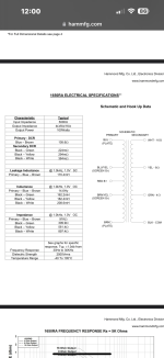
My question is, no matter how they're measuring, how is the stated primary inductance SO different? I've attached pics. Stated is that the entire primary of the Ra is only 14 Henries, but just one half of the R is 320 Henries? Are they measuring one at voltage and the other not, maybe? Measuring the Ra, P-P, I get the stated 14h.
Thanks so much for any info. Soon I'll start a thread for the build.
Attachments
Sounds about right to me. Inductance is not a constant - core is nonlinear. Will be much higher at 10V 60 Hz. Easy to measure - apply 10V AC with current meter in series. Calculate reactance from X=V/I. Convert to inductance L=2*pi*X
For a 5K P-P OT 320H would be an expected norm.
For SE, the ABYSMAL 14H might be seen on a VERY poor freq. response SE OT.
Barest (absolutely sucks) MINIMUM L:
2 pi f L = PriOhms
where f is the lowest freq.
14H would give minimum freq. of 57 Hz (for 5K Ohm) with large magnetizing current, not even suitable for a 60 HZ power xfmr. (smoking hot)
For SE, the ABYSMAL 14H might be seen on a VERY poor freq. response SE OT.
Barest (absolutely sucks) MINIMUM L:
2 pi f L = PriOhms
where f is the lowest freq.
14H would give minimum freq. of 57 Hz (for 5K Ohm) with large magnetizing current, not even suitable for a 60 HZ power xfmr. (smoking hot)
Last edited:
I'd go with Hammond's 320H (10V, 60 Hz) unless it measures otherwise. I measured a 6.6K/50W output transformer that I picked up at a hamfest - 715 Henries at 20 Hz, 10V. Leakage inductance was not great at 65 mH. Sold it as a guitar / bass amp transformer. Better high frequency than the Hammond though - they say 170 mH but don't say which tap - if it's 16 Ohms, others are typically higher.
Thank you Steve and Tom, I will get those measurements later on.
Depanatoru-Sounds like the 320H could be very real, measured at greater voltage and lower frequency
Smoking Amp- 2*Pi*F*L= Pri ohms. This means primary impedance, yes? And I know inductance is not fixed, so at what frequency/voltage would one measure the primary L to satisfy this equation?
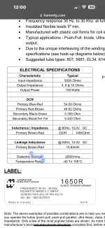
Tom, they say 170mH leakage for the Ra, and they do say which taps, they say that is for the entire primary. That's at 1v, 1khz. The lower, more normal leakage is listed for the old R, at 10mH. But again that's at 10v, 60Hz. And that one is for just half the primary. How can I test for the leakage current on this Ra? I might as well do that later on as well, when I'm checking the inductance at 10v 60Hz.
Thanks much guys. At least we can all see just how bad the new Hammond OPTs are. Should be good info for others, as this is what they sell now.
Loren
Depanatoru-Sounds like the 320H could be very real, measured at greater voltage and lower frequency
Smoking Amp- 2*Pi*F*L= Pri ohms. This means primary impedance, yes? And I know inductance is not fixed, so at what frequency/voltage would one measure the primary L to satisfy this equation?
Tom, they say 170mH leakage for the Ra, and they do say which taps, they say that is for the entire primary. That's at 1v, 1khz. The lower, more normal leakage is listed for the old R, at 10mH. But again that's at 10v, 60Hz. And that one is for just half the primary. How can I test for the leakage current on this Ra? I might as well do that later on as well, when I'm checking the inductance at 10v 60Hz.
Thanks much guys. At least we can all see just how bad the new Hammond OPTs are. Should be good info for others, as this is what they sell now.
Loren
Leakage inductance is measured across half primary with other half shorted and full primary with each secondary tap shorted. Lower the better. This is one spec that I hope is a typo - 170 mH at 20 KHZ is effectively 20K inductive reactance in series with 5K load.
Smoking Amp- 2*Pi*F*L= Pri ohms. This means primary impedance, yes? And I know inductance is not fixed, so at what frequency/voltage would one measure the primary L to satisfy this equation?
Yes, primary impedance. These impedance #s generally get measured with a 60/50 Hz Variac up around 50VAC. (check for primary V headroom at 60 Hz for a tiny OT, but 50 VAC is generally safe) Measure V and I to calc. the L#. The measured inductance is much smaller for tiny voltages, like with an L meter, due to the permeability curve for the iron. The 14H # above -could- be that initial inductance measured with an LC meter around the zero flux crossing. Then the L peaks up around 30% to 50% of Vmax for the OT (for 50/60 Hz) due to the material permeability curve peaking and also due to butt joints in laminations becoming active above 50% flux. (joints not an issue for toroids obviousy) The 50/60 Hz freq. is good since the distributed winding capacitance does not interfere much with the L measurement there. Setting an L meter up for 1 KHz or above will see the inductance come down due to winding capacitance. The low L meter reading (even at 60 to 100 Hz setting) is not usually given for OT specs, but it IS actually important, since that is what the output tubes have to deal with for zero crossings. One reason to use some local N Fdbk around the output stage to lower Zout there..
I use a 55 VAC isolated Variac (surplus find) for this. With a Tek current probe to a scope to check the OT primary current waveform. If it starts peaking sharply, then it is getting into the region of saturation, and I like to know just how much the -real- max power rating "should" be. The current goes from sine wave, to triangle wave to square and then square wave with spikes on the edges, from saturation setting in. You probably don't want spikes occurring in your Amp output, but you will find that virtually ALL OTs are spec'd for max power well up into the spiky region. Local N Fdbks to the rescue again! The current spikes are due to saturating magnetizing current, which doesn't show up directly in the output, but hits the output tube's Zout. Which then drops some voltage during the spike, unless Zout is low.
Last edited:
Yeah, kinda looks like someone fixed one typo in another place, creating two.This is one spec that I hope is a typo - 170 mH at 20 KHZ is effectively 20K inductive reactance in series with 5K load
It states 170mH at 1khz, not 20khz. And the old model R states 10mH, and that is taken at 10hz.Leakage inductance is measured across half primary with other half shorted and full primary with each secondary tap shorted. Lower the better. This is one spec that I hope is a typo - 170 mH at 20 KHZ is effectively 20K inductive reactance in series with 5K load.
And that makes sense Smoking amp. Indeed, the 14H reading that I get with this Ra model is obtained with a simple LCR meter. I'll be home here soon and take some measurements. And again thank you all so much for your time.
Loren
Thank you Steve and Tom, I will get those measurements later on.
Depanatoru-Sounds like the 320H could be very real, measured at greater voltage and lower frequency
Smoking Amp- 2*Pi*F*L= Pri ohms. This means primary impedance, yes? And I know inductance is not fixed, so at what frequency/voltage would one measure the primary L to satisfy this equation?
Tom, they say 170mH leakage for the Ra, and they do say which taps, they say that is for the entire primary. That's at 1v, 1khz. The lower, more normal leakage is listed for the old R, at 10mH. But again that's at 10v, 60Hz. And that one is for just half the primary. How can I test for the leakage current on this Ra? I might as well do that later on as well, when I'm checking the inductance at 10v 60Hz.
Thanks much guys. At least we can all see just how bad the new Hammond OPTs are. Should be good info for others, as this is what they sell now.
Loren
I'm not arguing with you , but if it has 14H measured with a LCR Meter that value matters in a practical amplifier , is impossible to obtain 320H with any honest approch ... just a stunt to confuse some customers I'm afraid .
But of course it is what it is , Hammond is just a budget transformer .
Last edited:

is impossible to obtain 320H with any honest approach
Have you measured one? I measured two smaller Hammond transformers (1609 and 1620) at 20 Hz, 10V and obtained 368 Hy and 232 Hy. Core permeability (inductance) increases at higher flux densities - to a point. Hammond rates most of their their transformers for full power at 30 Hz, which would not be possible if inductance was only 14 Hy at 30 Hz. There are better transformers around, and worse ones. I'd rather design around Hammond than the Acrosound ones I've measured, which had some nasty ultrasonic impedance gyrations.
I measured a lot of output transformers , if a LCR brige tells you it's 14H ( measured at 50/60Hz ) you can't bent the reality ... it is that bad in an amplifier . I don't know what you measured at 10V , put it than at mains voltage at least , closer to the working amplifier voltage at a resonable power .
And where is stated with measurements that is rated for full power at 30Hz ? Any Hammond graph is made at a ridiculous low power at which any transformer would be pretty good . Something like those 10V , which on 5K load is about 20mW ...
Very few comercial , old or new , amplifiers would give full power at 20Hz-30Hz , so in this regard wouldn't be so bad . Maybe surprising for many audiphiles that don't measure just read the advertised ratings .
Last edited:
Around the zero crossing, at millivolts like the LC meter uses, the tubes are loafing along with plenty of reserve "horsepower" , they just need some low Zout to let them "know" about and fix the magnetizing current problem. Either local or global N Fdbk will take care of it. Or a low Zout triode. It's not generally a problem for P-P. Maybe some of the power xfmr/toroids that occasionally get pressed in OT duty do. (not enough turns)
There is an (expired) patented scheme (by Audio Precision no less) patent # US4614914 which can remove magnetizing current altogether. It monitors the current driving the OT, at the tube, and uses some limited positive FDBK to pre-drive the tube(s) with a little extra V drive to just take care of the extra load. When the modified signal goes thru the OT, the xfmr strips off the extra part, leaving just the actual signal to pass thru the OT. It basically nulls out the primary resistance. So you get lower output Z for the whole amplifier too. Some local V NFDBK around the tube would also help make sure the tube is linear in applying that correction too.
( I don't think there are any tube Amps out there using this yet. I plan to test this in the Spring when I get my low Z Toroid 1200 Ohm OT in. Using 6528 tubes, so it can run as corrected OT or OTL. We'll see which has lower distortion. I'm pretty sure the corrected OT will win, hands down, with the impedance matching advantage. )
Last edited:
Clearly stated in the datasheet:And where is stated with measurements that is rated for full power at 30Hz ?
Maybe somebody would post measurements results in an amplifier ... and measured inductance at 50/60Hz , not sci-fi figures of hundreds of Henry
14,6H at 1KHz and 360H at 60Hz just half of secondary is not credible and physical impossible . Ohmic resistance is low too , so it doesn't have exceptional high number of turns
Even toroids don't have that inductance
14,6H at 1KHz and 360H at 60Hz just half of secondary is not credible and physical impossible . Ohmic resistance is low too , so it doesn't have exceptional high number of turns
Even toroids don't have that inductance
Last edited:
Take a look at Toroidy: 591HEven toroids don't have that inductance
https://sklep.toroidy.pl/en_US/p/TT...6,6kOhm-2xEL34-2x6L6-Push-pull-or-similar/562
Inductance on a cored inductor can vary with the test voltage.Sounds about right to me. Inductance is not a constant - core is nonlinear. Will be much higher at 10V 60 Hz. Easy to measure - apply 10V AC with current meter in series. Calculate reactance from X=V/I. Convert to inductance L=2*pi*X
Hi all. Depanatoru, I'm not arguing either, and I appreciate your time. As others have said, there are better and there are worse outputs. These, rated at full 100w 30-30k, I'm quite certain will be just fine for a 40-50w pp design. But just how good or bad, we'll see here soon.
Tom you had given these equations:
Calculate reactance from X=V/I. Convert to inductance L=2*pi*X
Plugging things in, I realized quickly that I must be missing something. 10volts divided by milliamps quickly gets to unrealistic numbers. Is I in milliamps, not amps?
So I looked and found another, L=V/(I/t). This made much more sense. I took a couple measurements. At 20V/60Hz I got 241H=20V/(.00134A/.016s). At 50V/60Hz I got 294H=50V/(.00272A/.016s).
Correct me if I'm figuring out time incorrectly (1/60). These sounded like much more realistic numbers.
Thank you all. Once I confirm this stuff I'll check out the leakage inductance.
- Home
- Amplifiers
- Tubes / Valves
- Hammond 1650RA primary inductance question