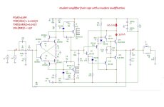
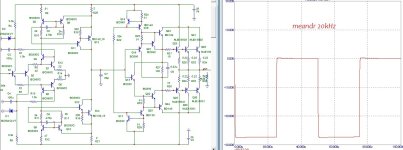
Attached is my 1991 student amplifier with a modern modification.
modifications:
*element base
*progressive correction
*optimization of modes
This is how the amplifier was assembled in 1991. Initially it was assembled by hanging installation, the initial current of the output stage was very small (10mA - Class B), now I have increased it a little.
power supply without a middle point, because The topology of the circuit is symmetrical with respect to the power supply and there is no need to base the elements on the power ground, so a virtual ground is formed.
For Q7 KQ8 small radiators are required, because It is necessary to dissipate 200 mW of heat on each transistor.
The thermal stability of the output stage is ensured by the arrangement of all Q9Q10Q11Q12Q13Q14 transistors on one radiator.
You can regulate the initial current by pairwise selection of resistors R19R21.
Maybe this scheme will be interesting for someone to repeat - it worked for me for about 10 years.
Attachments

The circuit is self-balancing, if feedback is removed from the output, the voltage will be no more than 1 mV, with NFB connected at the output 0.2 mVHow was the output DC offset ? Servo wasn't needed?
Yes, that’s right, since the GND is virtual, like in QUAD405 and other versions. In fact, I have not tried connecting bipolar power; in this case, protection for the speakers in the speakers must be done just in case. The project itself was an amplifier in Class B, with a Virtual GND in Class B , the amplifier sounds “more alive”.The only path for the speaker current return is via the reservoir caps?
You need to consider the thermal resistance between dies, packages, and heatsink.The thermal stability of the output stage is ensured by the arrangement of all Q9Q10Q11Q12Q13Q14 transistors on one radiator.
I estimate a 10x current increase in Q13 and Q14 with a 30C delta. The output transistors need emitter resistors.
Ed
I
I like vintage style amplifiers simple but powerfull.Attached is my 1991 student amplifier with a modern modification.
modifications:
*element base
*progressive correction
*optimization of modes
This is how the amplifier was assembled in 1991. Initially it was assembled by hanging installation, the initial current of the output stage was very small (10mA - Class B), now I have increased it a little.
power supply without a middle point, because The topology of the circuit is symmetrical with respect to the power supply and there is no need to base the elements on the power ground, so a virtual ground is formed.
For Q7 KQ8 small radiators are required, because It is necessary to dissipate 200 mW of heat on each transistor.
The thermal stability of the output stage is ensured by the arrangement of all Q9Q10Q11Q12Q13Q14 transistors on one radiator.
You can regulate the initial current by pairwise selection of resistors R19R21.
Maybe this scheme will be interesting for someone to repeat - it worked for me for about 10 years.
However,, the temperature gradient is negative, i.e. at +1 degree temperature -1 mA of initial current.You need to consider the thermal resistance between dies, packages, and heatsink.
I estimate a 10x current increase in Q13 and Q14 with a 30C delta.
Vintage is a relative concept, because... the circuit already contains modding and is far from the last, because the tracking supply voltage has not yet been implemented and the linearity of the input stage is not enough, which is why distortions after 1 kHz (which amount to 0.0005%) begin to quickly increase by 1 orders of magnitude, this is solely due to insufficient linearity of the input stage. But it sounded interesting, and even with a weak initial current of the output transistors it sounded very clean...I like vintage style amplifiers simple but powerfull.
I'm not sure I fully understand the consequences of that. It's something to think about and it's going to keep me awake now! I've designed a few op-amp circuits in the past, where the IC has no 0V connection, even some single rail circuits, but this seems different somehow!Yes, that’s right, since the GND is virtual, like in QUAD405 and other versions. In fact, I have not tried connecting bipolar power; in this case, protection for the speakers in the speakers must be done just in case. The project itself was an amplifier in Class B, with a Virtual GND in Class B , the amplifier sounds “more alive”.
Thanks for sharing.
As far as I remember, then it was indirect protection of the speakers of the acoustic system, because everything was tested on the model with hinged installation.I'm not sure I fully understand the consequences of that.
Maybe I'll try to assemble and check the bipolar power supply again. )))
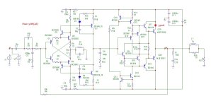
slightly upgrade the circuit:
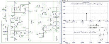
* The output stage is a structure of low-, medium- and high-power transistors , the initial current is 59 mA, which weakly depends on the supply voltage, the output stage is thermally stable with a negative gradient.
in this configuration of the output stage it was possible to obtain +6 watts more power, i.e. the output power is already 56 watts at a 4 ohm load.
*The input stage, with the addition of the R13C6 RC circuit, received an open loop gain of 96 dB. However, the configuration of the input stage has significant nonlinearity. Therefore, despite the fact that the voltage amplifier is a two-stage structure and relatively deep negative feedback, for high-quality and pleasant-to-hear sound you will have to look for another solution, because It is not possible to correct the nonlinearity of the input pairs of transistors of the voltage amplifier.
We'll keep thinking....
Attachments
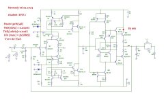
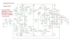
Please:The only path for the speaker current return is via the reservoir caps?
*bipolar power supply +/-36 volts, no servo required.
*0.1 Ohm resistors in the emitters of the output transistors, initial current 80 mA
*a converted voltage amplifier, which has a high overload capacity, i.e. at the input voltage is permissible up to 4 volts amplitude, i.e. like a tube cascade.
*as a result, the output power before the sine wave limitation increased to a crazy 130 watts at a 4 Ohm load with a power supply of +/-36 volts
- input stages are linear until covered by negative feedback,
- open loop gain is 80dB, pole 1kHz
- unity gain frequency 10 MHz
- progressive correction
- Slew rate 60 V/µs
Attachments
Last edited:
- Home
- Amplifiers
- Solid State
- student amp from 1991