Hello, I am simulating the response of a Monolith Magnetics SX-11 (Rpri = 330Ohm, Lp = 24H, Wingding ratio = 25.25) at low frequency.
For the simulation I assumed the source is a 300B tube with 800Ohm Rplate, and the load is a loudspeaker with Re 6.5Ohm a resonance peak at Fs=40Hz,
I modelled the 300B output with a current generator in parallel to Rplate, and the loudspeaker with at RLC equivalent circuit.
For the simulation, I only considered Rpri and Lp of the transformer since the effect of the stray capacitance is negligible at the low frequencies,

First I ran an impedance/frequency simulation of the speaker to verify that the model was correct and I got a 90KOhm peak at 40Hz seen from the primary of the transformer (equivalent to a 144Ohm peak on the secondary), which is what I was expecting.

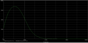
Then I simulated the frequency response of Vload/Vplate and this is where things look to good to be true: the simulation shows large +.6dB peak centered around Fs=40Hz (see image below) which pushes the -3dB frequency below 3Hz.

Of course, the simulation doesn't take into account of the saturation of the core, but this still looks too good to be realistic.
Am I missing something in the simulation or doing something incorrectly?
BTW.. if I replace the loudspeaker model with a resistor R=5K I get still a very low -3dB frequency at lower then 3Hz.

For the simulation I assumed the source is a 300B tube with 800Ohm Rplate, and the load is a loudspeaker with Re 6.5Ohm a resonance peak at Fs=40Hz,
I modelled the 300B output with a current generator in parallel to Rplate, and the loudspeaker with at RLC equivalent circuit.
For the simulation, I only considered Rpri and Lp of the transformer since the effect of the stray capacitance is negligible at the low frequencies,
First I ran an impedance/frequency simulation of the speaker to verify that the model was correct and I got a 90KOhm peak at 40Hz seen from the primary of the transformer (equivalent to a 144Ohm peak on the secondary), which is what I was expecting.
Then I simulated the frequency response of Vload/Vplate and this is where things look to good to be true: the simulation shows large +.6dB peak centered around Fs=40Hz (see image below) which pushes the -3dB frequency below 3Hz.
Of course, the simulation doesn't take into account of the saturation of the core, but this still looks too good to be realistic.
Am I missing something in the simulation or doing something incorrectly?
BTW.. if I replace the loudspeaker model with a resistor R=5K I get still a very low -3dB frequency at lower then 3Hz.
Attachments


Rplate is not in series if you model the source as a current generator (see Northon's Theorem).Internal Rplate is obviously in series with the generator and higher than 800ohm , this is the source of low frequency roll off
Learn more ... a tube is not a current generator in the first place , why put a voltage generator then ?
@euro21
Rpp = 1Meg <= irrelevant
Cp = 299p <= irrelevant at LF
The major differences I see between your simulation and mine are:
Rplate = 1700 in your simulation (I used 800 ohm and my value might not be accurate)
R3 = 8ohm <= This is a gross approximation at LF, because speaker drivers behave very far from an ideal 8ohm resistive load near resonance. They usually have a peak of resistive impedance that can go as high as 100ohm near resonance, depending on the driver.
Learn more ... a tube is not a current generator in the first place , why put a voltage generator then ?
@Depanatoru
First:
"A vacuum tube, electron tube,[1][2][3] valve (British usage), or tube (North America),[4] is a device that controls electric current flow in a high vacuum between electrodes"
https://en.m.wikipedia.org/wiki/Vacuum_tube
Second:
"Norton’s theorem states that any linear circuit can be simplified to an equivalent circuit consisting of a single current source and parallel resistance that is connected to a load."
https://www.allaboutcircuits.com/textbook/direct-current/chpt-10/nortons-theorem/
Before saying "learn more" to someone, you should educate yourself.
There is nothing more obnoxious than an ignorant who thinks to know better than people who went to school and studied the subject.
It is incredible how the people run with simulation without any basic infos!!
Read Radiotron in the trafos sections then use real world not simulation
Each trafo is a world apart!!!
Walter
Read Radiotron in the trafos sections then use real world not simulation
Each trafo is a world apart!!!
Walter
Hello, I am simulating the response of a Monolith Magnetics SX-11 (Rpri = 330Ohm, Lp = 24H, Wingding ratio = 25.25) at low frequency.
For the simulation I assumed the source is a 300B tube with 800Ohm Rplate, and the load is a loudspeaker with Re 6.5Ohm a resonance peak at Fs=40Hz,
I modelled the 300B output with a current generator in parallel to Rplate, and the loudspeaker with at RLC equivalent circuit.
For the simulation, I only considered Rpri and Lp of the transformer since the effect of the stray capacitance is negligible at the low frequencies,
View attachment 1266751
First I ran an impedance/frequency simulation of the speaker to verify that the model was correct and I got a 90KOhm peak at 40Hz seen from the primary of the transformer (equivalent to a 144Ohm peak on the secondary), which is what I was expecting.
View attachment 1266752
Then I simulated the frequency response of Vload/Vplate and this is where things look to good to be true: the simulation shows large +.6dB peak centered around Fs=40Hz (see image below) which pushes the -3dB frequency below 3Hz.
View attachment 1266754
Of course, the simulation doesn't take into account of the saturation of the core, but this still looks too good to be realistic.
Am I missing something in the simulation or doing something incorrectly?
BTW.. if I replace the loudspeaker model with a resistor R=5K I get still a very low -3dB frequency at lower then 3Hz.
View attachment 1266761
View attachment 1266761
Wrong equivalent circuit
Read some articles in Italian on Audioreview about trafos so you can learn a lot
I will give you specs about them
Walter
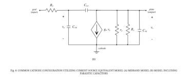
@waltube For the transformer, I used the LF equivalent model from "Transformers for Tube Amplifiers" by Igor S. Popovich.
And for the tube model I referred to
http://bear.ces.cwru.edu/eecs_cad/tut_spice3_tube.html
Do you have a more accurate equivalent circuits you want to share?
And for the tube model I referred to
http://bear.ces.cwru.edu/eecs_cad/tut_spice3_tube.html
Do you have a more accurate equivalent circuits you want to share?
Attachments

Last edited:
If you can’t see the differences you need to study in deep the theoryDo you have a more accurate equivalent circuit you want to share?
Read Radiotron RH4 (as told you) first of all the the other books
Depanatoru and Euro21 gave you the answer
Walyer
Why would there be any difference if a current or a voltage generator model for the tube is used?
Wouldn't using the Norton or Thevenin equivalent be the same?
Wouldn't using the Norton or Thevenin equivalent be the same?
Last edited:
A current generator with a resistor in parallel and a voltage generator with a resistor in series are equivalent.
https://www.allaboutcircuits.com/textbook/direct-current/chpt-10/thevenin-norton-equivalencies/
https://www.allaboutcircuits.com/textbook/direct-current/chpt-10/thevenin-norton-equivalencies/
A load resistor is not equal with a impedance ( inductive for the transformer ) , we are not talking about simple DC circuits ...
@Depanatoru I am not sure what you are talking about. In the model I used above, the transformer inductance is modeled by Lp.
I'm not sure what you understand from electronic active devices as amplifiers ... the tube is a natural voltage AC generator with internal resistance Rp , the load is a impedance , you can't transform it in a AC current source with a parallel resistor as you did ... can be transformed in theory but is more complicated and pretty useless for understanding how this circuit is working .
I think you are confusing the static DC current in tube with the AC analysis - totally different
I think you are confusing the static DC current in tube with the AC analysis - totally different
Last edited:
The right equivalent circuit is the one from Depanatoru not from himAt first sight, nothing seems out of order.
And he is not able to see the differences
Walter
@Depanatoru
If I replace the current generator with a voltage generator, the result is the same. I might be omitting a high pass component in the model, I am not sure..


@waltube fa meno l'arrogante vala'
If I replace the current generator with a voltage generator, the result is the same. I might be omitting a high pass component in the model, I am not sure..
@waltube fa meno l'arrogante vala'
- Home
- Amplifiers
- Tubes / Valves
- Simulate OPT SX-11 at low frequency