Hello, I designed a new pcb for a quality amplifier circuit, I tested it, the sound is good, the bass is strong.


Attachments


Rather neat documentation.
I'm wondering whether this schematic is rather old. TL071 is known to be a bit noisier than other newer parts. Say even older NE5534? MJ15003 was great stuff in 1988, but since all ON semi TO3 parts cost the same I wonder why you didn't use MJ21194 or MJ15024? Or save $5 apiece by using MJL21194 or MJL4281?
Furthermore most PA amps in the 300-500 W class have VI limiters. My woofers cost >$230 each, an extra transistor is paltry compared to that. Clipping limiter on the front end is complicated but highly useful for fighting the tendency of bar bands to drive the guitar into square waves and burn speaker windings.
Of course the DC detection & speaker relay can be outboard.
Last edited:
The schematic is very old. 🙂 Didn't work with TL071 (+-15v crashed), fake or defective. I used LM741 instead and it worked without any problems. I don't have NE5534P. MJ21194 transistor and others are very expensive here 🙁
This is actually very old/classic Servo DC idea, and it can actually be reliable like nothing else for driving subwoofers in hard conditions(festivals, idiot owners(night clubs), rave party...). It is crude design and not best amp choice for hi/mids. This amp type must have DC protection in case servo fails.
Sch below is same type amp, but made for professional use and reliable operation, and it does it for 20years min. It was originally derived from some crest amplifier models by reverse enginnering 30+years ago in communist Croatia/Yugoslavia because of import bans on electronics, so they were forced to make equipment by themselves and somehow smuggle motorola MJ transistors into country.
It was real revolution in communist amps and replaced quasi 2N3773 designs available. Everything was hand made in Croatia(including toroid and case) by company COBRA-TON for over 30years. In few years COBRA-TON hand made and owned the most powerful P.A system in Europe for next 10years, and holds record in Croatia to this day.
This amplifier was installed in many night clubs, but was also sold to many P.A. rental companies and bands. After many(20+) years they still work in many clubs and bands, so I reverse engineered the amplifier schematic in order to make clones since circuit is very reliable yet simple. Original amp had DC/temp protection and fan speed regulation and bridging option, details and sch of these on my blog(written on Croatian).
Most powerful Logic Sound model LS2000 had two of these boards in larger case, and every board had one more pair of transistors per ch(4 per board) so they can drive 2ohm loads because 2ch pcb is now single amplifier channel made by bridging both channels on every pcb. LS2000 was least reliable when driving 4ohm loads all night, so they later reduced it into LS1600 with lower psu voltages and other mods to make actual channels more reliable driving 2ohm.
Man who assembled probably hundreds of these amps has retired years ago and we don't have his contact info or know where he is. Man who designed this schematic and PCB has passed avay last year. If someone has time and will to design pcb similar to this original one, I would appreciate It because i lack time for it🙂
If I manage to get my hands on LS2000 model I will post pics of internals .


More about this amplifier on my blog (CRO)
.jpg")
.jpg")
Sch below is same type amp, but made for professional use and reliable operation, and it does it for 20years min. It was originally derived from some crest amplifier models by reverse enginnering 30+years ago in communist Croatia/Yugoslavia because of import bans on electronics, so they were forced to make equipment by themselves and somehow smuggle motorola MJ transistors into country.
It was real revolution in communist amps and replaced quasi 2N3773 designs available. Everything was hand made in Croatia(including toroid and case) by company COBRA-TON for over 30years. In few years COBRA-TON hand made and owned the most powerful P.A system in Europe for next 10years, and holds record in Croatia to this day.
This amplifier was installed in many night clubs, but was also sold to many P.A. rental companies and bands. After many(20+) years they still work in many clubs and bands, so I reverse engineered the amplifier schematic in order to make clones since circuit is very reliable yet simple. Original amp had DC/temp protection and fan speed regulation and bridging option, details and sch of these on my blog(written on Croatian).
Most powerful Logic Sound model LS2000 had two of these boards in larger case, and every board had one more pair of transistors per ch(4 per board) so they can drive 2ohm loads because 2ch pcb is now single amplifier channel made by bridging both channels on every pcb. LS2000 was least reliable when driving 4ohm loads all night, so they later reduced it into LS1600 with lower psu voltages and other mods to make actual channels more reliable driving 2ohm.
Man who assembled probably hundreds of these amps has retired years ago and we don't have his contact info or know where he is. Man who designed this schematic and PCB has passed avay last year. If someone has time and will to design pcb similar to this original one, I would appreciate It because i lack time for it🙂
If I manage to get my hands on LS2000 model I will post pics of internals .
More about this amplifier on my blog (CRO)
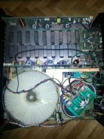
> LS1600 model/variant - internals
Attachments
Rather than just try to copy the existing board, work from the schematic and design the PCB around whatever heat sink you might happen to HAVE. It is not all that complex a design, and could even be re-done around the flat pack (MJL) versions of the transistors to make it less of a nightmare to assemble. Add an extra pair of outputs if using flat packs.
Well, your idea is actually good because then I would make driver board which controls output transistors that are on separate pcb, so you can make pcb for TO-3 and another one for plastic packages and just customize it for heatsink you have. Also original board has many flaws like too weak relays in DC protect for this sized psu, no short protection on amp out, no voltage regulator on 24v auxiliary winding to make sure something wont be blown by overvoltage(i once meausered 30V on it!) and this amp doesnt contain single fuse, rail fuses are must have for me, speaker fuse can also save you something if calculated properly. Also this amp uses heatsinks to distribute pwr rails to output transistors and via transistor's screws to many places on board which is not very good solution because between two sinks is 150V DC!! There is no soft start circuit so you can't turn it on because it blows the automatic fuse most of the time. There are some parts on pcb that never had these parts soldered in, and since guy who designed it passed avay we will never know what is purpose and what parts go there so no point to draw these on new pcb.
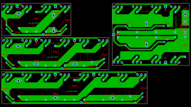
Here is SCH of DC protection, fan psu and input pcb which is used for bridging, volume adjusting and making balanced input sig. unbalanced. Photo of this pcb is below, it very simple and I can confirm that it actually works great(I cloned this board and use it in other projects).


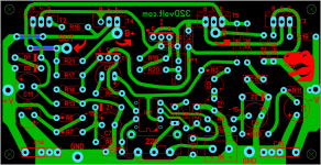
HQ photos of main pcb with no blue jumper wire that I installed because trace was broken.


Here is SCH of DC protection, fan psu and input pcb which is used for bridging, volume adjusting and making balanced input sig. unbalanced. Photo of this pcb is below, it very simple and I can confirm that it actually works great(I cloned this board and use it in other projects).
HQ photos of main pcb with no blue jumper wire that I installed because trace was broken.
I'm very interested in this kind of amps but very few design available on the net. Recently i repaired an opamp based amplifier which turn out very quiet(low noise). It uses 4558 as opamp, darlington pairs in the driver stage & 5200/1943 at the output. Although all parts were of dubious quality but it performed really well.
Output bjt's reversed, watch out, MJ21196 is an NPN device, the other suppose to be MJ21195 but number 9 was omitted, please check and correct your schematic.Well, your idea is actually good because then I would make driver board which controls output transistors that are on separate pcb, so you can make pcb for TO-3 and another one for plastic packages and just customize it for heatsink you have. Also original board has many flaws like too weak relays in DC protect for this sized psu, no short protection on amp out, no voltage regulator on 24v auxiliary winding to make sure something wont be blown by overvoltage(i once meausered 30V on it!) and this amp doesnt contain single fuse, rail fuses are must have for me, speaker fuse can also save you something if calculated properly. Also this amp uses heatsinks to distribute pwr rails to output transistors and via transistor's screws to many places on board which is not very good solution because between two sinks is 150V DC!! There is no soft start circuit so you can't turn it on because it blows the automatic fuse most of the time. There are some parts on pcb that never had these parts soldered in, and since guy who designed it passed avay we will never know what is purpose and what parts go there so no point to draw these on new pcb.
Here is SCH of DC protection, fan psu and input pcb which is used for bridging, volume adjusting and making balanced input sig. unbalanced. Photo of this pcb is below, it very simple and I can confirm that it actually works great(I cloned this board and use it in other projects).
View attachment 1265291
View attachment 1265292
View attachment 1265293
HQ photos of main pcb with no blue jumper wire that I installed because trace was broken.
View attachment 1265309
View attachment 1265308
Thanks for pointing out these errors and sorry for first sch, I have already redrawn this sch some time ago, and forgot I have posted here first version of it. Here is same schematic, but fixed:

In the meantime, I also finally managed to get one LS1600, to see the differences between variants, and It looks like they changed some things(more simple with one IC and different output transistors driving). Also heatsinks are isolated from voltage and protection is on another board, input pcb seems little more complex, but amp itself sounds harsh especially in hi mid and hi, compared to the LS1000 variant. This one was for subs probably since it is real powerful. Here I give you some photos, if community is interested in this and similar amps I may open new thread for more detailed info. I have many of these old but gold forgotten amplifiers with no info about them on the internet.


In the meantime, I also finally managed to get one LS1600, to see the differences between variants, and It looks like they changed some things(more simple with one IC and different output transistors driving). Also heatsinks are isolated from voltage and protection is on another board, input pcb seems little more complex, but amp itself sounds harsh especially in hi mid and hi, compared to the LS1000 variant. This one was for subs probably since it is real powerful. Here I give you some photos, if community is interested in this and similar amps I may open new thread for more detailed info. I have many of these old but gold forgotten amplifiers with no info about them on the internet.
- Home
- Amplifiers
- Solid State
- 500W Driver