The 10uF or whatever will have enough stray inductance in its leads and structure that it has a 'self resonant freqeuncy' (SRF) where it looks like a RLC combination.
Above that frequency it's generally poor as a capacitor.
Likewise inductors often have a spec'd SRF above which they are likely useless.
All the components in a speaker and crossover have non-linear tendencies, so they can a) generate high frequencies and b) detect high frequencies.
So it's a good idea to decouple any high frequencies.
An extreme case I saw many years ago, a speaker with just a cable connected to it would 'receive' CB radio transmissions from the house next door. I guess it was an illegal AM set.
I wonder if one thing which can happen might be the woofer being over driven putting spikes on the tweeter?
Maybe more likely spikes on the mains go right through an amp and appear at the speaker.
Or the speaker wires might pick up from things like mobile phones, or the motor of a hoover going over them?
In the instrumentation world, it's generally good practice to limit the bandwidth of interfaces.
Anyone who's had a hard time getting a product through EMC certification shouldn't be surprised that a 100n cap can be a shilling well spent.
I have an amp from a well known brand with little ceramic caps across the speaker terminals inside. Factory fit I think, but I didn't buy it new.
If you've got an oscilloscope, turn the timebase all the way down and have a look at those speaker wires.
You might find things you don't want to see and you might make them go away with a small C.
The problem with these kinds of EMC scenarios is often that there are too many variables to always make tests repeat.
It's maybe something we should think about if we are using products and designs from last century, when people didn't have 4G phones or Wifi TV.
Bear in mind that a 100n cap may have rolled over and died well below the GHz bands.

The problem is don't think in terms of lumped reactances at audio frequencies. Think about transmission lines at however many MHz an amplifier or its output stage might be able to oscillate at, even if it just little bursts of oscillation at particular operating points. Rectification in junctions can cause bias shifts and or other problems.The inductance and capacitance of several feet of speaker cable will likely negate the effect of any small value capacitor in a speaker crossover.
Air cored inductors are linear, metal film resistors are linear, film caps are linear - its only electrolytics you have to worry about and good quality bipolar electrolytics are the least distorting sort. Yes the speaker coil itself has non-linearity, its not easy to avoid that.All the components in a speaker and crossover have non-linear tendencies
Not really, electrolytics and speaker coils don't have cross-over distortion, bipolar electrolytics and speakers are not rectifying.so they can a) generate high frequencies and b) detect high frequencies.
metal film resistors have excess noise which is signal correlated if the current follows the signal. Not all film caps are linear, such as some mylar. Also, IME other film caps can have linear distortion related to DA.metal film resistors are linear, film caps are linear -
Electrolytics can be low distortion if the AC voltage across them is small enough, but some may produce current noise when used for coupling.
Just saying, linearity isn't everything. That said, one salient thing about PSS nonlinearity is that its easy to measure.
All of them, including metal film. Good metal foil is probably the best in that regard. Some metal film come pretty close, other metal film not so much. Of course, it depends on the application how much is too much.
The point you may be missing is that your speaker components may be significantly non-linear at RF.
It's not just about a cosy world of simulating things up to 20kHz, the real world is GHz of electromagnetic activity.
It's not just about a cosy world of simulating things up to 20kHz, the real world is GHz of electromagnetic activity.
To what effect?The point you may be missing is that your speaker components may be significantly non-linear at RF.
I would worry at RF anything only if it causes any audible effect within the Audio band.
Otherwise ... it becomes irrelevant by definition.
Otherwise ... it becomes irrelevant by definition.
"To what effect?" the answer to that will depends on a lot of things, at best, 'nothing significant' at worst maybe something which sounds like mains-borne noise, clicks, tones, whatever.
There are loads of reports of mobile phones interfering with audio equipment for instance.
I've never put any hifi through EMC compliance testing, but I've seen all sorts of hard to explain failures with other equipment.
Any interface with a long unscreened wire hanging out of it would be a prime suspect.
Yes, that's radiated EMI/RFI. If there is nonlinearity involved, its usually in forward biased semiconductor junctions, which can function as small signal rectifiers, modulators, and or demodulators.There are loads of reports of mobile phones interfering with audio equipment...
Best thing to do is try it and see what happens! It’s a small investment and if it doesn’t make it sound better to you, you can use the caps elsewhere.
A power amplifier ringing or oscillating in the low megahertz range is never a good thing.I would worry at RF anything only if it causes any audible effect within the Audio band.
Otherwise ... it becomes irrelevant by definition.
Attachments
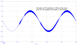
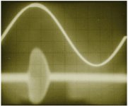
The second picture is from Cyril Bateman's article on blowing up power amps with seemingly decent cables: https://www.waynekirkwood.com/images/pdf/Cyril_Bateman/Bateman_Speaker_Amp_Interaction.pdf
That is a fascinating article. The moral appears to be "don't design speaker cables to act like low-impedance transmission lines".
In RF, transmission lines are always terminated into their characteristic impedance to prevent the transmitter's output energy from being reflected back into the transmitter (which would cause a disaster). Apparently, audio amplifiers are susceptible to the same problem. The audio amplifier's own negative feedback is creating the RF energy.
Ed
Last edited:
I agree, it's a fascinating article thanks to DSP Geek for the link.That is a fascinating article. The moral appears to be "don't design speaker cables to act like low-impedance transmission lines".
In RF, transmission lines are always terminated into their characteristic impedance to prevent the transmitter's output energy from being reflected back into the transmitter (which would cause a disaster). Apparently, audio amplifiers are susceptible to the same problem. The audio amplifier's own negative feedback is creating the RF energy.
Ed
How would you design a speaker cable not to look like an RF transmission line?
You could design it to look like a higher impedance RF line, but that might make it better at picking up stray RF.
It should be possible to filter the speaker connections at the amp. The passband might need to go up to some tens of kHz? The stop band might have to include long wave, but the serious problems might start in the MHz?
A few simple ferrite beads which become very lossy in the MHz area and above maybe?
Some work on matching the line to the speaker was done by @Hans Polak in another thread. https://www.diyaudio.com/community/threads/zip-cord-for-speaker-test.371099/
Turns out the TL impedance needs to be low for the speaker not to cause reflections.
Turns out the TL impedance needs to be low for the speaker not to cause reflections.
Higher (>100 ohm) cable impedance is fine. Impedance matching works only for pure resistive loads. The problematic cable not only couldn't match the speaker but had so much capacitance as to destabilize the amplifier.
A good amplifier should not pick up RF from its output.
Ed
A good amplifier should not pick up RF from its output.
Ed
Back on topic re the use of bypass capacitors in loudspeaker crossovers -speaking purely historically a lot of it can be traced back to JBL in the '70s, who were using primarily mylar / MKT type caps (some bipolar electrolytics also) for the main values on most of their filters, including those in the high-end HE systems with compression mids, HF units etc. They initially started off shunting these with 0.068uF MKP types, borrowing the notion from its use in electronic circuit design. They later moved to 0.01uF MKPs, and in extreme cases, 0.01uF MKP with an additional 0.005uF polystyrene shunt. The caps were regular industrial types & cost peanuts -in fairness to JBL, they never claimed otherwise AFAIK. The underlying assumption was that the main value caps suffered from hysterisis effects and that bypassing them with smaller caps of nominally greater linearity compensated / corrected for that, especially if dissimilar dielectrics were used.
So there you go -that's where a lot of it came from. I never saw any proof, and it's likely that it gave their marketing department something to say that sounded 'technical' -although it's interesting that many of the enthusiasts for these systems when rebuilding their crossovers actually say they prefer the bypassed mylars to single-value MKPs. Go figure on that. Greg Timbers, who's hardly a fool, stuck with it for years, although IIRC his last word on the matter was 'buy the best caps you can afford and charge couple them', even though he stressed the latter actually increased IM distortion slightly.
So there you go -that's where a lot of it came from. I never saw any proof, and it's likely that it gave their marketing department something to say that sounded 'technical' -although it's interesting that many of the enthusiasts for these systems when rebuilding their crossovers actually say they prefer the bypassed mylars to single-value MKPs. Go figure on that. Greg Timbers, who's hardly a fool, stuck with it for years, although IIRC his last word on the matter was 'buy the best caps you can afford and charge couple them', even though he stressed the latter actually increased IM distortion slightly.
Last edited:
- Home
- Design & Build
- Parts
- Science of "bypass capacitors" in crossovers