Hi members,decided to reach-out as I am "hitting a wall" with the repair of a NAD 7020 amplifier section.
This is the second version with the separate boards via connector.
Here is a summary:
Disclaimer: someone was previously messing around with this unit, so I got it non functional:
This is the second version with the separate boards via connector.
Here is a summary:
Disclaimer: someone was previously messing around with this unit, so I got it non functional:
- Entire unit has been recapped.
- Tuner section and preamplifier are now working fine.
- Voltages on power supply are within specs.
- Amplifier driving stage not sure if working properly.
- Previously the output stage transistors were all shorted, they have been replaced with 2N3055G & MJ2955G (epitaxial).
- The BD139 have been replaced with 2SC2690A.
Attachments
When you say "The BD139 have been replaced with 2SC2690A" - I assume you are talking about both BD139s (both the one in the VAS (Q607/Q608) and Vbe multiplier(Q609/Q610)?
At the stage where you are I would:
- verify the BIAS and DC offset behaves the same way in left and right channels
-> in the hope only one channel behaves badly in which case you have a "bad" and a "good" to compare
If both channels are behaving badly:
- Using the variac: try to establish whether the Vbe-multiplier seems to be working (including measuring R655, R641, R643 and Rx 1) - Vbe on the BD139 should get to around 0.6V and stay there.
BTW: at what supply voltage do you see the urealistic BIAS and offset?
And when you say "unrealistic" - what does that mean?
Cheers, Martin
Last edited:
Slow/variac start up voltages are rarely "graceful", especially when operating under 40% mains voltage, part of the reason why the power on mute feature was introduced. Suggest try power up with variac and current limiter (DBT), and monitor bias, slowly increase variac while DBT remains dull, note if voltages normalize somewhat. If all ok then remove DBT and repower up on a variac and push through the somewhat concerning amps. My yamaha A-1 would hit about +/-15Vdc at emitters during variac power up.
Hi Martin, Yes Q607/Q608/Q609/Q610 have been replaced with 2SC2690A.When you say "The BD139 have been replaced with 2SC2690A" - I assume you are talking about both BD139s (both the one in the VAS (Q607/Q608) and Vbe multiplier(Q609/Q610)?
At the stage where you are I would:
- verify the BIAS and DC offset behaves the same way in left and right channels
-> in the hope only one channel behaves badly in which case you have a "bad" and a "good" to compare
If both channels are behaving badly:
- Using the variac: try to establish whether the Vbe-multiplier seems to be working (including measuring R655, R641, R643 and Rx 1) - Vbe on the BD139 should get to around 0.6V and stay there.
BTW: at what supply voltage do you see the urealistic BIAS and offset?
And when you say "unrealistic" - what does that mean?
Cheers, Martin
Both channels are having near identical behaviour.
All components have been checked, I am hesitant to power at full voltage, I tried with a DBT and Variac and you can see the light bulb getting brighter consistently as I increase the voltage, my common sense and experience tells me (after having fried the 1 ohm resistors on both sides and blow F1 & F2, that there is a short somewhere.
By unrealistic I mean over 0.5 Volts of DC on speakers terminal at very low AC and BIAS going all over the place.
Or try adding series resistors between amp and each power supply rail to limit the current - many solid-state circuits won't behave at low voltage so you could be chasing shadows. Try a few hundred ohms series resistors initially (and no load), with bias backed off, see if the amp's trying to pull large currents (if not and the output voltage is reasonable can try lower value resistors and upping the bias).
That allows full voltage operation with little risk of blowing the outputs and drivers if something's wrong.
That allows full voltage operation with little risk of blowing the outputs and drivers if something's wrong.

I would really recommend checking post #8Hi Martin, Yes Q607/Q608/Q609/Q610 have been replaced with 2SC2690A.
Both channels are having near identical behaviour.
All components have been checked, I am hesitant to power at full voltage, I tried with a DBT and Variac and you can see the light bulb getting brighter consistently as I increase the voltage, my common sense and experience tells me (after having fried the 1 ohm resistors on both sides and blow F1 & F2, that there is a short somewhere.
By unrealistic I mean over 0.5 Volts of DC on speakers terminal at very low AC and BIAS going all over the place.
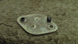
Removed all 8 screws with nuts (I did not have any insulators or fiber washers to start with) now the collectors of the output transistors are left "hanging". Measuring voltage on 1 ohm collector resistance without any difference. Measuring resistance between ground (heat sink) and collector of:
2N3055 both open loop.
MJ2955 8.5 Mohm
In reference to post #8: I had a similar problem with a Yamaha M-45 where the thermal pads (the ones without thermal grease) were conductive and basically a resistance between collector and ground. Is it possible that the grey silicone grease is causing a problem ? I checked for conductivity and it is ok, may be possible capacitive.
Mica insulators must be present. Transistor case is live(=collector so at rails voltage)Removed all 8 screws with nuts (I did not have any insulators or fiber washers to start with) now the collectors of the output transistors are left "hanging". Measuring voltage on 1 ohm collector resistance without any difference. Measuring resistance between ground (heat sink) and collector of:
2N3055 both open loop.
MJ2955 8.5 Mohm
Needed to measure the case to heatsink resistance with screws in place, the screws MAY be providing the low resistance path to GND
Some formulations of thermal paste contain low levels of silver so they can be conductive however this does not appear to be the case since,Is it possible that the grey silicone grease is causing a problem
2N3055 both open loop.
MJ2955 8.5 Mohm
Just to be clear, with collector screws removed, the DBT should be dim and there should not be any abnormal voltage at the speakers.
Back at it after a client repair I needed to complete.
Removed all output transistors, re-tested again with Atlas DCA55 (no problem).
Checking voltages going backwards from output transistors, the voltage between ground and collector of Q612 or Q614 (RH channel) is 50% of the opposite pair. Removed C625,6,7&8 tested out of circuit (within specs). Applied the same voltage with the capacitors removed, no difference.......the hunt for the short continues.
I think my first steps with this would be to apply a short across the vbe multiplier to force zero bias and then power up using a bulb tester on full mains and see where it is at voltage wise.
This looks to be very similar to a basic 3020 type output stage and these are not great for DC stability being single ended at the front end. If the supplies are altered (variac etc) the DC offset can be pretty large.
This looks to be very similar to a basic 3020 type output stage and these are not great for DC stability being single ended at the front end. If the supplies are altered (variac etc) the DC offset can be pretty large.
Hi, I hope you have made progress with this repair. I am also working on one of these and had to remove the front plate to replace the treble pot. As you also removed the front plate, I wonder if you drew a diagram of the dial string arrangement? If so, please can you post this, as my string came loose before I had a chance to draw the diagram! My bad, I know.
- Home
- Amplifiers
- Solid State
- NAD 7020 Stubborn repair