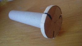
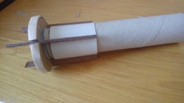
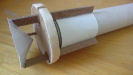
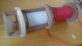
Hi everyone .
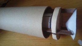
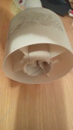
I made a cardboard model to show you what I thought. the images in this case are indispensable .
it is a field coil loudspeaker which does not have the circular cut (air gap) which completely interrupts the magnetic flux.
in this case, however, the magnetic flux manages to close through three paths that join at the center (2). This is the great advantage.
but there are also disadvantages. the voice coil is located further away, it is more difficult to design the path for the voice coil terminals.
the winding of the voice coil is not located outside the support but inside, the three rods serve to join the voice coil to the loudspeaker cone (actually the cone you see in the image is small and must be glued to the cone than the loudspeaker which is much bigger ). I believe it is possible to do everything in carbon fiber with a 3D printer (1).
the red wire you see (5) is the winding that creates the magnetic field.
finally everything is placed inside a hollow cylinder to create the ring in which the flow closes (6) .
do you think it works?
Attachments

I don't think that would work, or at least not very well. Your voice coil would not be in an area of high magnetic flux. You need the air gap so that you can direct the magnetic field through the voice coil. Your design would keep all the magnetic flux inside the steel circuit.
Peavey has line of woofers where repair kits look this wayAre loudspeaker manufacturers willing to sell their product without a permanent magnet?
Attachments
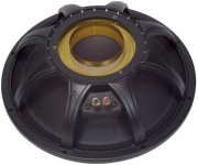

The Peavey field replacable cone and basket makes me wonder what the price breakdown is for the assorted parts of a pro driver. Guessing the magnet structure is the most.
The magnetic field would be going the wrong way. You need flux lines going through your voice coil in the same plane of the windings and perpendicular to the windings to generate axial force to move a cone. This is a bad description, but if you have a magnetic field oriented along the same axis as the voice coil, you will generate force inwards and outwards on the coil. Look up the right hand rule for Lorentz force for a better explanation.in this case they would be two concentric magnetic fields
I've always heard about Lorenz's right hand rule and strength but my head has always refused to believe it. Obviously you're right, otherwise it wouldn't explain why everyone does this. it would be wanting to deny the laws of physics. but explain one thing to me though, because two linear permanent magnets placed on the same axis attract and repel each other according to the orientation of the poles? . obviously everything changes between the permanent magnet and the winding.
could this work?
the magnetic field is formed inside the circular toroid made up of 4 elements each fed individually, image16.
electric current flows within strips of thin metal perpendicular to the magnetic field, image18.
the magnetic field is formed inside the circular toroid made up of 4 elements each fed individually, image16.
electric current flows within strips of thin metal perpendicular to the magnetic field, image18.
Attachments


Hi,
Best is to get and to learn FEMM freeware, and you will soon see what works and what not.
Best regards
Mattes
Best is to get and to learn FEMM freeware, and you will soon see what works and what not.
Best regards
Mattes
it takes a long time to learn all the functions of a software from scratch. Is there anyone kind enough to do a simulation for me?.
If I understand your idea correctly, yes, that could work. If you create a circular magnetic field in your toroid and have current flow from outside to inside through the gaps in the toroid that would generate force aligned with the centerline of the toroid. It seems pretty complicated though. What do you see the advantage being? You'd probably want to keep your conductive strips to be short in the direction of current flow so you don't have a bunch of extra resistance that isn't generating force. You'd have a bunch of structures that would be tough to make stiff enough to not resonate in undesirable ways, I would imagine.
yes you understood correctly. the main advantages that come to mind are two. absence of inductance or superfluous. the air gap can be greatly reduced compared to the traditional system, perhaps less than half a millimeter because in this case there is no thickness of the support and the copper wire. perhaps with this system instead of a copper strip metal as a conductor, new materials such as graphene could be experimented with. If I understand correctly the Lorenz force one of the factors it depends on is the speed of the electrons and in graphene it seems to be 100 times greater but more in-depth studies need to be done. regarding the structure, it can be done in carbon fiber with 3D printer. but all this is to be verified.
Hey, I know I am late to the party, but I want to make sure I am understanding something correctly here.
I have been running around like a mad man for the past couple weeks trying to find an affordable source of pure iron. I have sent several quotes off with very little response.
I am looking to get 4 pieces of 82mm diameter rounds that are 12.5mm thick and I have been looking for plate iron that I can cut down to size, or a large diameter round bar that I could cut slices out of.
I have been looking for pure iron since it seems to saturate at around 2.2T. My goal is to be able to hit 2T. I was dissuaded from trying 1018 steel because it could saturate as low as 1.6T. But now I am reading some other sources that it can saturate as high as 2T and change.
Considering the low cost and ubiquity of 1018 steel, would it be worth a shot?
Hi Tjj,
Sorry for the late reply.
As you may have read, I make my motors entirely from pure iron. The supplier is Puron Metals
https://puronmetals.de/en/
for Europe (can´t see from where you are...)
and they sell pure iron steel bars, which I have never seen nor touched, as they go directly to my cnc manufacturer.
Pure iron saturates at 2,18T, and depending on motor geometry and magnet force it can be saturated (my motors are fully saturated). But of course this is not what you will have in the airgap. My airgap has 1,3mm with a length of 10mm and a diameter of 40mm, and I have (measured, not guessed) 1,54T in the airgap. Pure iron was the best compromise, it is expensive, but not extremely so as Permendur, which would have costed much more and could have resulted in app. 0,1T to 0,15T more in the airgap. That´s it. Whenever you read of claims or advertisments of 2,3T in the airgap - don´t believe it, it´s not possible. Physics.
1018 steel is standard. A bit better results are possible with 1010 steel, but Pure Iron is still better and allows to have around 10% more power in the airgap. FEMM is a great tool and will show you what´s possible and what´s not possible. The simulations are pretty precise and match reality quite good.
All the best
Mattes
Attachments


Thank you for the reply. That is very insightful.
I am in the USA, and I have tried reaching out to various suppliers of pure iron. The best option I have so far is Allied but unfortunately they do not sell small batches. I saw your post about your supplier in germany. I am waiting on a few more quotes to come back, but if they do not give me a favorable reply, I am going to reach out to your supplier and see if they will do international shipping.
I have used FEMM for a few ideas, but I do not know how to model my design since it isn't clear how you would model a multi winding magnet. I want to try a design similar to the one in this picture below. Mine is a little bit smaller and uses 6 coils in a hexagon pattern. I have 0.5 inch silicon fm b round rods for the 6 core pieces and a 1 inch pure iron rod for the main pole piece. It's just the top and bottom plate I am struggling with. I can get a metal plate from mcmaster carr, but they don't guarantee a specific alloy. They say it will be between 1006 and 1026 but will aim for 1008. So I am at the mercy of a lottery system.
What about Aliexpress?
https://www.aliexpress.us/item/3256...730ea2&afSmartRedirect=y&gatewayAdapt=glo2usa
I was thinking of trying this source for some pole pieces for motors I started.
After discussing it with the person who’s design I am copying I settled on 1010 steel for the pole and regular A36 mild steel for the rest of the motor parts.
They were able to achieve as much as 1.5 or 1.6T with this design, but said ideally 1.1-1.2T was the sweet spot anyway…and they were using the same materials.
Yeah, I have looked there a lot. The best I found was a 100mm diameter soft iron bar (similar to the one in your link) but it was almost 300 bucks. If I could get a solid 4 pieces out of it to make my two drivers, it wouldn't even be that bad, but since you have to account for the kerf of the bandsaw blade, I would only get 3 half inch (12.5mm) pieces.
Im honestly surprised that A36 works even that well. You guys have given me the confidence to buy the plate I need from McMaster Carr. https://www.mcmaster.com/6544K37/
I should be able to cut 9 pieces out of that. So 1 set of speakers as a reference. 1 set for experimenting. And 1 spare piece just in case.
Once I have a reference pair made, the other thing I am curious to try is to make the top and bottom plates out of laminations. Send Cut Send can make some thin laminations for cheap and can be used to make some more complex shapes without needing to spend a ton on CNC work. Would laminations hurt the magnetic strength? Would adding different metal sheets improve the performance without raising the price so drastically? I think the only way to know for sure is to test it out.
Hi Tjj,
Yes, I think MOQ for pure iron is a 1000mm bar, and it is not cheap.
The only way I´m aware of to model your design in FEMM would be a recalculation as an axial motor, but I ma ybe wrong.
If the question is allowed: what is the reason for the 4 coils? What advantages do that have, or what are you going to achieve, compared to a more conventional design? I can see thermal and ventilation benefits, sure.
Please don´t get me wrong, no offense intended, just want to know!
All the best
Mattes
I am pretty hard to offend 🙂
Any multi coil approach (I am doing 6 coils) has the benefit of thermals and ventilation. But in my case the main attraction is cost and ease of production. My design should cost less than 100 usd per completed speaker driver (In theory if I make washi paper cones, I should be right around 60 usd per driver) and only require a band saw and a drill to produce it.
The easier and cheaper it is to make, the easier it will be to iterate on the design.
- Home
- Loudspeakers
- Multi-Way
- Project Ryu - DIY Field Coil Loudspeaker