I don't know why everything can be easily solved on the internet. But for me, it's not like this. Someone buys online an luxman amplifier from Japan , when receive amp .....it doesn't have a fuse. After installing the fuse, the amp has problem. ! Let's go see what the problem is?
mq-80 has 2 of 6336 in output . The current of 6336 increases and the amp turns off in 1 or 2 min .It seems that they tried to fix the problem, but they didn't succeed, and the is amp sold as it is.

pot 30 k + 30k is dc balance .
mq-80 has 2 of 6336 in output . The current of 6336 increases and the amp turns off in 1 or 2 min .It seems that they tried to fix the problem, but they didn't succeed, and the is amp sold as it is.
pot 30 k + 30k is dc balance .
Please look carefully, technical friends. The method of protection is unusual. connecting the gate of the thyristor to the main voltage by capacitor... how can overload be detected? Does the amplitude of the ripples can trig the thyristor ?
Last edited:
The coupling capacitors prior to the cathode follower driver stage may be leaking.
To verify, just remove both of the coupling capacitors in the channel, and see if the problem is still there.
To verify, just remove both of the coupling capacitors in the channel, and see if the problem is still there.
Last edited:
Does the amp stay on when you power it up without any tubes inserted ?
If it does, check if all the ps voltages are what they should be.
If powersupply voltages seem ok, insert the 12bh7 and power up with a stepped down main input voltage.
Luxman choosed to operate tubes partly above specs at normal operation conditions, and when operating
with the 6336 not inserted, voltages will increase even more.
Please check out the tube manufacturers published voltage limits, it is risky to exceed them by too much.
Check, and make notes of the 12bh7 voltages and of the adjustment range of each 6336 grid voltage.
If ok, insert the 6267 and 6aq8 and power up again and repeat 6336 grid voltage measurement.
If the 6336 grid voltages are all alike and things changed only in proportion to ps voltage changes
adjust to the MAX negative grid voltage.
Then try again with also the 6336 tubes inserted.
Measure the grid voltages again, and check if the all changed proportional to the changes in anode voltage
the same way proportional or is there a difference do to possible grid leak?
Does power stay on?
If it does, power up with full main voltage and adjust each grid for the specified cathode current.
Good luck.
Last edited:
This amplifier came to you from Japan?
Was it made to use on Japan's 100VAC Power Mains?
And, is your Power Mains 120VAC?
Then get a 120VAC to 100V step down transformer (do not cheat, that transformer has to be able to deliver at least the same amount of VA and Watts that the amplifier draws.
The Schematic of Post # 2, shows a 100VAC primary.
Problem Solved?
I have an adjustable transformer and I have 100 volt power. And also in this case all voltages are correct. 6336 plate voltage is about 250v.
When there is no output tubes, the amplifier turns on after a minute .....and stays on. I used a 6080 tube to more protection. But the output current still rises and I turn off the amplifier. When the current rises, There is no change in the negative voltage of the pin 1 and pin 4.!!!!!!
, the bias voltage is- 84 and the current is 50 milliamperes... but in my amplifier, with a bias voltage of -110 volts, the current goes to 100 ma and more!!!!
I changed the coupling capacitors... First.The coupling capacitors prior to the cathode follower driver stage may be leaking.
To verify, just remove both of the coupling capacitors in the channel, and see if the problem is still there.
Thank you for your reply. Everything is normal. Except the output current. V of pin 3 and 6 changes without changing the negative bias voltage in pin 1 and 4 . The tubes are new. I could hear the sound of the amp before the amp shuts down.previous owner has changed power tubes sockets.Does the amp stay on when you power it up without any tubes inserted ?
If it does, check if all the ps voltages are what they should be.
If powersupply voltages seem ok, insert the 12bh7 and power up with a stepped down main input voltage.
Luxman choosed to operate tubes partly above specs at normal operation conditions, and when operating
with the 6336 not inserted, voltages will increase even more.
Please check out the tube manufacturers published voltage limits, it is risky to exceed them by too much.
Check, and make notes of the 12bh7 voltages and of the adjustment range of each 6336 grid voltage.
If ok, insert the 6267 and 6aq8 and power up again and repeat 6336 grid voltage measurement.
If the 6336 grid voltages are all alike and things changed only in proportion to ps voltage changes
adjust to the MAX negative grid voltage.
Then try again with also the 6336 tubes inserted.
Measure the grid voltages again, and check if the all changed proportional to the changes in anode voltage
the same way proportional or is there a difference do to possible grid leak?
Does power stay on?
If it does, power up with full main voltage and adjust each grid for the specified cathode current.
Good luck.
Do you have a scope to check if there is some weird oscillation?
Oscillation or carbon deposite from partly burned OPT is about the only thing I can thinck of.
Take out the 6336 to make sure there is no OPT prob with current leaking from anode to cathode winding
Oscillation or carbon deposite from partly burned OPT is about the only thing I can thinck of.
Take out the 6336 to make sure there is no OPT prob with current leaking from anode to cathode winding
Last edited:
i have oscope i check for any oscillation . checked opt in dc ohm and h. evrything is normal. japanes owner tried to fix but ....!!!Do you have a scope to check if there is some weird oscillation?
Oscillation or carbon deposite from partly burned OPT is about the only thing I can thinck of.
Take out the 6336 to make sure there is no OPT prob with current leaking from anode to cathode winding
IIRC, this amplifier originally featured proprietary power tubes that couldn't be replaced by more common ones like 6080's or 6336's. Maybe that's the issue's cause?
Best regards!
Best regards!
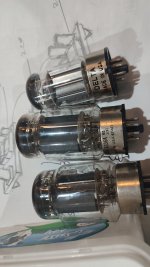
both triodes in 6336 is completely similar. There is no disconnection. . The current chang by the adjustment of the bias pot, but , the problem is not fixed.
, the repairs started with 6336. just in ten seconds,amp went into protection mode. 6080 like 6336 but with less power. It creates more time for voltage measurement.IIRC, this amplifier originally featured proprietary power tubes that couldn't be replaced by more common ones like 6080's or 6336's. Maybe that's the issue's cause?
Attachments
Many times in this forum, I saw friends send posts about the electrical characteristics of tubes
.. But no one likes the analysis of the circuits. Does anyone know howLaxman made protect by this circuit?
n13t1 is Programmable Unijuntion Transistor....luxman used this transistor for 30 s to 40s for time and turn on scr in+250 line . when curent of output tubes gos up ... relay cuts off the load from the thyristor for one second and the thyristor turns off. It takes 30 seconds to turn on again.
- Home
- Amplifiers
- Tubes / Valves
- biasing 6336 in Luxman MQ-80 ...