I considered that approach when developing my Williamson PCB, but abandoned it for several reasons--1) The extra hours of work involved in wiring the sockets to the board, not to mention the awkwardness and added space requirements; 2) the fact that I wanted the board to do most of the work for an amateur builder; 3) adding to the length and complexity of the signal path; 4) the increased chances of miswiring, and possibly blowing the whole board at first turn-on; 5) the difficulty of modifying or even replacing the board in case such things should be desired or necessary. I agree about the "death grip" but that's why I went with the socket standoffs as suggested by the guy who designed mine. The Beltons surely do grip the tubes, which is a good thing, but the standoff arrangement reduces the chances of any strain on the board. So far mine have worked just as I intended them to.

Hello all,
First of all thank you so so so much for all your kinds advice's 😊
I'll try my best:
- Lead space for C3 C4 C5 and C6 is ok those Jantzen cap have the same length
How do you determine the value of those caps ? You said they were based on the output transformer, I have the hammond with me so maybe I can do some measurement or math ?
- I Changed the 1 Ohm 5W by 1W 0.5% (I have those here, if 1W is too much I'll buy them)
- For the KT88 screens, I have at home Welwyn W20 7W 130 Ohm, is it ok ? Or maybe there is a way to determine the correct value? for the power of the resistors, those KT88 screens eat like 10mA max (4.6W) so 7W is more than ok ?
- I added space around the FB leads
- I Added way more space around the 360VAC leads
- The CT is now linked to C10neg
- I tried to do a star ground style
- For the Heaters I have 2 nice "Ohmite 100 Ohm 5W WHE100FET" Do you really prefer a Pot ?
- For the Patrick Turner's current feedback technique, I'm not sure to have sufficient knowledge , I'm not equipped with monitoring tools 🤔
- L1/L2 Yes they are gonna be chassis mounted, about the Ripple trap, how do you determine the value of the RC combination ?
- I'll had two little chokes "30H 1KOhm" between A+ and B+, but first i need confirmation of the Voltages:
According to my simulation
KT88 => 470-460V // 280mA max
PI => 430V // 10mA
V1B => 340V // 5.25mA
V1A => 300V // 4.4mA
V4 Rounded:
I tried to follow your advice's I'm sorry if I missed one 🙄


Schematic remind:

Best regards
First of all thank you so so so much for all your kinds advice's 😊
I'll try my best:
- Lead space for C3 C4 C5 and C6 is ok those Jantzen cap have the same length
How do you determine the value of those caps ? You said they were based on the output transformer, I have the hammond with me so maybe I can do some measurement or math ?
- I Changed the 1 Ohm 5W by 1W 0.5% (I have those here, if 1W is too much I'll buy them)
- For the KT88 screens, I have at home Welwyn W20 7W 130 Ohm, is it ok ? Or maybe there is a way to determine the correct value? for the power of the resistors, those KT88 screens eat like 10mA max (4.6W) so 7W is more than ok ?
- I added space around the FB leads
- I Added way more space around the 360VAC leads
- The CT is now linked to C10neg
- I tried to do a star ground style
- For the Heaters I have 2 nice "Ohmite 100 Ohm 5W WHE100FET" Do you really prefer a Pot ?
- For the Patrick Turner's current feedback technique, I'm not sure to have sufficient knowledge , I'm not equipped with monitoring tools 🤔
- L1/L2 Yes they are gonna be chassis mounted, about the Ripple trap, how do you determine the value of the RC combination ?
- I'll had two little chokes "30H 1KOhm" between A+ and B+, but first i need confirmation of the Voltages:
According to my simulation
KT88 => 470-460V // 280mA max
PI => 430V // 10mA
V1B => 340V // 5.25mA
V1A => 300V // 4.4mA
V4 Rounded:
I tried to follow your advice's I'm sorry if I missed one 🙄
Schematic remind:
Best regards
Last edited:
Which amplifier schematic are you going to build?
The one in Post # 19?
Are you going to use a PCB, or are you going to use point to point wiring?
Amp schematic in #19, PSU schematic and PCB in #22.
@Orion24 is developing this project.
I got your attention and the attention of Tim on it because you guys are my favorite experts!!
I asked @ra7 and @alexcp for their attention on the PCB because they are my heroes for that kind of work.
Regarding the coupling cap values, the ones in my schematic have been tested in numerous Williamson designs with various output transformers. They're designedto offer good low frequency stability within the circuit itself. If the output transformer doesn't have enough primary inductance to remain stable with 20dB feedback, it doesn't belong in a Williamson. ;-) From all I have read of the Hammond 1650NA it will work fine. The trick will be the high-frequency stability, and that will have to be done with the low-pass filter in the first stage andf the phase-lead cap across the feedback resistor.
Regarding the filament pot, you don't really need it in this design. The designer of my PCB added the blancing resistors but I don't use them. There's nothing wrong with having one, but it's not needed. I ground the 6.3V center tap.
Regarding a choke in the power supply, most Williamsons use 7-10H @ 150mA. For this higher-powered Williamson I think 5H at 200mA will be sufficient for each channel. The value isn't really critical, IMO.
I defer to Tim on the current feedback, I don't know anything about it.
Voltage dropped across the 130R screen grid resistor with screen current 10ma is (I = V/R) 0.01 x 130 = 1.3V.- For the KT88 screens, I have at home Welwyn W20 7W 130 Ohm, is it ok ? Or maybe there is a way to determine the correct value? for the power of the resistors, those KT88 screens eat like 10mA max (4.6W) so 7W is more than ok ?
Power dissipated is (P = IV) 0.01 x 1.3 = 0.013W.
There is a case to use a low wattage device so it is destroyed if there is a serious runaway of the tube and screen current goes very high.
Having googled a bit 2W seems to be a common suggestion in the guitar world, but I would think 1W is plenty. Main thing to consider is the voltage spec, and that is usually greater on a higher wattage component.
At the beginning i used this data to determine the consumption:

That's why I took 2 big chokes but those 280mA represent the MAX MAX signal and I'll never push that hard ! Don't want to loose ears.
My power transformer does have a center tap but it provide only 8A, so I'll use an other transformer to provide the 800mA missing or maybe there is room for, I don't know tolerances of that kind of transformer.
Wow I did so wrong... thank you OldHector, in my guitar amp I use all the time 5W but you are right I need to be careful with voltage tolerance, I'll change it on the PCB layout. As it's a Grid resistor should I go with carbon ?
Last edited:
@ElArte, I by far am not an expert on tube circuits, so take this with a grain (or two) or salt. Looking at the PCB artwork, I am a bit puzzled by the grounding scheme. Thin traces carrying signal ground are surrounded by polygons that are, apparently, some other ground - what's the idea behind this? If I were routing this (remember, I am not an expert), I'd make a classic wide ground bus from the point where R20 and R21 connect, to the point where R9 R10 R11 and the ground of B+ cap connect, then to where R7 connects to the ground end of C+ cap, then to R2 R3 and the ground end of D+ cap connection point, and then to each of input ground and feedback ground (feedback needs some reference point as does input, but I don't see feedback ground connection on the PCB).
@ElArte, I by far am not an expert
As always, you are too humble. Thanks for your feedback.
Hello Alex, well long time ago a friend working in the electronic industries told me by adding a copper plan as close as possible to signal trace will help to reduce noise, I used this technique few time in my guitar amps and if I link those copper planes to the GND it remove a lot lot of noise but maybe in HIFI world I don't need that ? You are not the first one to be puzzled by this 😆
The feedback ground is now labeled and visible near the FB pads
I also tried to find a solution for the Bias circuit and the KT88 GND's to avoid as much a ground loop


I'm not an expert too it's my +/- 10th pcb only so still learning
But I think I'm gonna rework the GND of the preamp tubes to flow directly to there main 30uF cap but as the board can be use for both channel its difficult 🤔
The feedback ground is now labeled and visible near the FB pads
I also tried to find a solution for the Bias circuit and the KT88 GND's to avoid as much a ground loop
I'm not an expert too it's my +/- 10th pcb only so still learning
But I think I'm gonna rework the GND of the preamp tubes to flow directly to there main 30uF cap but as the board can be use for both channel its difficult 🤔
Last edited:
Hi. That is an interesting pcb design you’ve got. Schematic is very similar to one of my last tube amps. If I may suggest something that I have found very good to have: change R8 to 15k and add a 10k single turn trimpot, series with R8.
When you power up the amp you can adjust the trimpot for lowest THD or better - you can adjust the harmonic response to make H2 predominant and H3 very low.
Regards,
Mircea
When you power up the amp you can adjust the trimpot for lowest THD or better - you can adjust the harmonic response to make H2 predominant and H3 very low.
Regards,
Mircea
change R8 to 15k and add a 10k single turn trimpot, series with R8.
I'm a big fan of such trimpots.
Thank you for the tip Mircea, it's added 😊
Last version for today, I cleaned a lot of traces and started to move some stuff on the power supply pcb


Ps: I hope its not an issue to post so much images 🙄
Have a nice day
Last version for today, I cleaned a lot of traces and started to move some stuff on the power supply pcb
Ps: I hope its not an issue to post so much images 🙄
Have a nice day
Onion24, in general, my comments may relate to subtle, and quite technical concerns, with consequences that are likely 'down in the weeds' and not audible, but I've included them all the same, and perhaps of some benefit to others. Some comments may be difficult to 'design in' part values up front, or reconcile if they are really needed to be added to your pcb in particular, or a pcb in general. You have particular parts in mind, whereas my comments are aimed more generally - so please don't feel obligated to make changes if it is not what you want for your pcb.
Ground pours on pcbs are worthwhile, but caution is needed if they add to stray capacitance from high-impedance circuit nodes to gnd - such as under C3, C4, or when very close to signal traces such as related to V1/1, and V2/1 and /4. Such stray capacitances reduce the very high frequency corners that are inherently introduced by valve and valve base stray capacitances, and may add phase shift in the hundreds of kHz region where stability is often determined.
Over time (due to 'pollution'), and sometimes due to solder flux, the margin between a pad or signal line, and the ground pour can introduce leakage, especially for higher voltage nodes and B+ feeds. You may want to review your pcb as to the margin separation used. Noise per se can certainly be a dominant issue for digital and instrumentation/smps analog circuitry, and tight margins are often worthwhile, but they are typically related to commercial product, relatively low voltage, using an overlay resist, and where stray capacitance is not an issue. As a sanity check, valve amps by their nature are a different beast, and where parts were commonly hung in free air between terminals in regions fairly close to large transformer cores with mains and high signal voltages. So consideration is needed when vintage and modern practices come together.
With respect to pcb dimensions, you may be able to relocate (now) C7's to the sides and lower the HT diode group and then allow the bias parts to fit in, without having to enlarge and make a difficult pcb shape.
Wrt screen stoppers for the KT88's, I would typically include them for fault protection. Because they can fail if a tube screen fails, or they can fail from serious overdrive in say a guitar amp, I think many have tried to make such a resistor more robust by increasing resistor wattage rating. This is quite a technical area if the resistor aims to survive worst-case nominal use, as compared to a failing screen. Screens conduct for half a signal cycle, and the peak current depends on configuration, and the resistors ability to survive, or not, depends on the resistor part chosen. Part values are typically kept low for hi-fi, so as not to introduce screen voltage sag (which can be a benefit for some guitar amps), so voltage drop is normally low, and the part does not normally have to cope with excessive voltage in a UL configuration.
Vintage coupling cap values such as 10-50nF and 250nF may allow motor-boating style instability, especially when the OPT primary inductance related corner frequency is not low enough. Dave Gillespie (over on Audiokarma forum) showed that making the first set of coupling caps quite high in value can push their frequency corner to well below the OPT corner, and hence suppress their contribution to overall phase shift, and avoid any form of motorboating. Making the second set of coupling cap values relatively small, eg. 100nF or 10%, may also alleviate blocking distortion type effects during overload compared to vintage 250nF. But it all depends on the OPT chosen, and that may take measurement unless others have field tested an OPT.
Given that parts may need to be changed 'along the way', it can be worthwhile making the pads and traces as beefy as practical (on both sides) to minimise pad and trace lifting or damage if/when parts are changed.
Ripple trap operation and tuning is discussed in: https://dalmura.com.au/static/Choke measurement.pdf. Perhaps easiest to use an on-line LC resonance calculator for cap value calculation.
Hum mechanisms related to heater powering are discussed in: https://dalmura.com.au/static/Hum article.pdf. In many instances, no perceived benefit may be gained from using a pot humdinger, compared to a fixed ct connection or fixed humdinger to gnd, or for heater elevation. And you may need more than a scope to appreciate any differences, but it can depend on the 6SN7 you have available.
I started a thread on using Patrick Turner's current feedback in: https://www.diyaudio.com/community/...ity-improvement-with-current-feedback.405089/
Ciao, Tim
Last edited:
Regarding the grounding of your design, I can suggest the way I am designing my pcb’s for tube amps. I am not claiming that this is good or bad - for me it is functional with very good results.
I am using ground plane on the top copper layer. Make sure you have thermal relief for the component pads connected to ground. I am running the heaters AC for the output valves with the traces on the bottom pf the pcb, on the edge of the board. The heaters for the small valves, always are fed with DC.
Noise floor of the amplifiers is always less than -90dB unweighted.
I hope this helps.
I am more than happy to help to the best of my knowledge, in case you need in the future of this project.
Regards,
Mircea
Good Morning / Afternoon / Evening So much time zone here 😆
Thank you Tim and everyone for your lights 😊 I printed your PDF its a gold mine !! I'll work and try to understand the Ripple trap.
As I'm still a newbie here I listen very carefully all the advice and apply then and of course I'll keep some personals touch on this pcb
For the screen KT88 stoppers I'lll put finally a 100Ohm 2W 600V rated and I'll have in case also 47 Ohm same specs and it should be ok not too big to burn as a fuse and well voltage calibrated
For the 6SN7 i'll take the 6SN7GTB Tungsol they seems to be good
I just receive the main transformer and it's big 7Kg ! Not use to that kind of transformer haha

For the Power supply coupling caps,
So i ran some PSU simulations and to keep the voltages stables even with a current increase I'll have to put a way more strong first cap to be stable enough, it need 1000uF min and now I have a doubt, should i put 3 350uF 550V JJ (but more expensive) or one big monster of 1300uF 600V like this one: https://www.mouser.fr/ProductDetail...f0viD3Y3bXvgfG2gej75s%2B5FookJ0JiG0tm8W83eA==
Into the datasheet it's written it can be used for "smoothing" or "demanding power supplies" so it can be ok ? And of course I'll add with this one something like 1uF polarized and 1 or 2 MKP10 film XXXn of even 1uF to help the big one to charge quicker and as you said I should making the first set of coupling higher I think it's gonna be the case 😆 And for the second stage of coupling after the choke I'll keep "only" 200uF
Concerning the PCB no review tonight but these are the change I'm gonna do:
- Moving back the Bias Supply and keep the big lines on top to have a good distribution and no ground loop
@KDMAudio
- Follow Mircea advices and do a GND top copper plane it'll be easier, for preamp only but in this case what space do you put between pads and copper ? at least 1.5 2mm nope ?
Again and again thanks a lot for your help 😊
Regards
Alexis
Thank you Tim and everyone for your lights 😊 I printed your PDF its a gold mine !! I'll work and try to understand the Ripple trap.
As I'm still a newbie here I listen very carefully all the advice and apply then and of course I'll keep some personals touch on this pcb
For the screen KT88 stoppers I'lll put finally a 100Ohm 2W 600V rated and I'll have in case also 47 Ohm same specs and it should be ok not too big to burn as a fuse and well voltage calibrated
For the 6SN7 i'll take the 6SN7GTB Tungsol they seems to be good
I just receive the main transformer and it's big 7Kg ! Not use to that kind of transformer haha
For the Power supply coupling caps,
So i ran some PSU simulations and to keep the voltages stables even with a current increase I'll have to put a way more strong first cap to be stable enough, it need 1000uF min and now I have a doubt, should i put 3 350uF 550V JJ (but more expensive) or one big monster of 1300uF 600V like this one: https://www.mouser.fr/ProductDetail...f0viD3Y3bXvgfG2gej75s%2B5FookJ0JiG0tm8W83eA==
Into the datasheet it's written it can be used for "smoothing" or "demanding power supplies" so it can be ok ? And of course I'll add with this one something like 1uF polarized and 1 or 2 MKP10 film XXXn of even 1uF to help the big one to charge quicker and as you said I should making the first set of coupling higher I think it's gonna be the case 😆 And for the second stage of coupling after the choke I'll keep "only" 200uF
Concerning the PCB no review tonight but these are the change I'm gonna do:
- Moving back the Bias Supply and keep the big lines on top to have a good distribution and no ground loop
@KDMAudio
- Follow Mircea advices and do a GND top copper plane it'll be easier, for preamp only but in this case what space do you put between pads and copper ? at least 1.5 2mm nope ?
Again and again thanks a lot for your help 😊
Regards
Alexis
Hello Alexis
Good choice with Piemme Elektra. You will be surprised. I am using custom transformers made by them.
Regarding the min clearance for the ground plane, I am going with 0.8mm. I know some gentlemen may recommend more, but this is only my option.
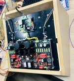
Please bear in mind that I am not routing HV traces on the top no matter what. 🙂
Good choice with Piemme Elektra. You will be surprised. I am using custom transformers made by them.
Regarding the min clearance for the ground plane, I am going with 0.8mm. I know some gentlemen may recommend more, but this is only my option.
Please bear in mind that I am not routing HV traces on the top no matter what. 🙂
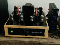
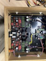
Wow your amp look so nice and nicely done !! Love the wood chassis style, how is it inside ? I'm curious 😊
I discovered Piemme Elektra one week ago because of they discount of 10% ! But if you are happy with them I'm gonna be happy too and they are not so expensive compared to others.
I'll root all the gnd on top and keep signal and HT on bottom without any copper there and for the clearance 1.3mm seem perfect not copper inside the socket and nice space around everything.
- Home
- Amplifiers
- Tubes / Valves
- First HiFi Tube amp