Zoran, the buffer between the DAC and transformer is a Musical Fidelity X10 clone - see this thread.
https://www.diyaudio.com/community/threads/x10-clone-tube-buffer-with-6n1p.402747/
The specs are in post #4 (R7 on the first schematic is incorrect, should be 470k)
It runs from +- 35-40v and uses a pair of PCC88s with 12.2v heater supply for the best results. (post #20)
https://www.diyaudio.com/community/threads/x10-clone-tube-buffer-with-6n1p.402747/
The specs are in post #4 (R7 on the first schematic is incorrect, should be 470k)
It runs from +- 35-40v and uses a pair of PCC88s with 12.2v heater supply for the best results. (post #20)
I saw but that it is not a buffer at all? This is sort of diferential input stage. And I think that this circuit has gain...Zoran, the buffer between the DAC and transformer is a Musical Fidelity X10 clone - see this thread.
I am pretty sure that there is no 200ohm output resistance because it is not a cathode follower style. Output signal is taken from anode with feed-back to cathode of first section.
I suggest to rearrange for real cathode follower buffer with gain=1, parallel sections, and you will get even lower ouput resistance of app. 1/(2xS) about 100ohms for ECC88 tubes.
.
That is why You have huge cutt-off in the bass with huge phase shift too with that circuit...
.
Measure primary inductance of the transformer with secondary open and secondary shorted with theese 1minute measurements you can calculate needed output resistace of transformer driver and coupling factor for HF...
Last edited:
It is a SE buffer so one stereo pcb will be needed for each channel to provide the differential output to the Sowter.
The LF on rolls off when the transformer secondary load is too low.
A 47k+ load is high enough to increase the reflected primary load on the buffer so there is no roll off until 35Hz.
I'll try using the NAD next to see if the roll off and phase are improved even more.
The only thing I wonder about, is the second triode appears to rely on grid leak biasing. I guess they chose it because of the limited supply voltage.
The X10 was called 'The Missing Link' by MF and is just a buffer than runs from 12v.
They probably used the same design in the M8 DAC which had a SS/Tube output switch.
That's a different question. IME ultra-low phase noise clocks don't do much for average consumer dacs. They may help some, but the effects tend to be pretty subtle. OTOH, IME if you take a SOA dac (maybe think, one of Bruno Putzeys' Mola Mola dacs, something in that league), then if you replace the clocks he put in it with consumer dac clocks, there will be an obvious degradation of the audio. Why? IMHO most dacs have enough other things non-ideal about them that the clocks aren't their worst problem....if not, what am I missing here?
Regarding THD+N as a metric, it has been dismissed as a useful metric even for simple amplifiers going back as far as to 1938. Sean Olive and Earl Geddes are two experts who have pointed out that THD+N/SINAD is useless as a metric for representing the degree of disagreeableness of the sound of an audio device.
DACs (sigma-delta, oversampling, DSD, etc.) are far more complicated than simple amplifiers in terms of the noise and distortion mechanisms that typically go on inside them. There are specialized measurements to evaluate their performance, but for some of the distortion and or noise mechanisms there are not to my knowledge published thresholds of audibility for them. That would be the case for close-in phase noise in particular.
What does that mean? What is your "method" of listening for a fingernail dragging across a blackboard?...no one has provided a convincing method of listening for it.
Could You please understand that main factor for LF roll-off is low inductance of transformer primary in relation to high driver output resistance?It is a SE buffer so one stereo pcb will be needed for each channel to provide the differential output to the Sowter.
The LF on rolls off when the transformer secondary load is too low.
A 47k+ load is high enough to increase the reflected primary load on the buffer so there is no roll off until 35Hz.
I'll try using the NAD next to see if the roll off and phase are improved even more.
The only thing I wonder about, is the second triode appears to rely on grid leak biasing. I guess they chose it because of the limited supply voltage.
The X10 was called 'The Missing Link' by MF and is just a buffer than runs from 12v.
They probably used the same design in the M8 DAC which had a SS/Tube output switch.
As inductance is lower the bigger LF cut off will be.
As the output resistance is to high to drive existing inductance the lower LF cut-off will be bigger...
.
There is nothing about the secondary load.
Secondary load will decrease all bandwidth if it is too low, as it will does the almost the same without transformer too...
.
So crucial information is primary inductance.
The output resistance of the dac with present R values are 25K.
Which model of sowter transformer is in use?
I am using the 9545 (superceded by the 1465) 5H inductance 10:1 step up ratio as I have currently connected them for dual TDA1541 differential I/V.
https://www.sowter.co.uk/specs/1465.php
I've already shown that the response is about -20db at 30Hz with a 22k load on the secondary and -4db with a 47k load.
I'll post some charts soon.
https://www.sowter.co.uk/specs/1465.php
I've already shown that the response is about -20db at 30Hz with a 22k load on the secondary and -4db with a 47k load.
I'll post some charts soon.


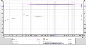
Measurements from the NAD's preamp.output.
X10 >> Sowters >> NAD CD input >>> NAD preamp output, vol at 75% through a 20d attenuator to the Behringer audio interface.
Just need to get the DAC ordered...


X10 >> Sowters >> NAD CD input >>> NAD preamp output, vol at 75% through a 20d attenuator to the Behringer audio interface.
Just need to get the DAC ordered...
You have hugh damping -db because of losses... If You measured with same signal level?
Also for this application sowter transfoermer is better to be configured as as low as posibile step up.
So connect primaries in series and secondaries in parallel. That will be 1:2.5 step up.
Because the dac already has the higher output vltage.
.
And 3H+3H=6Hy of primary inductance (doubled value) with total (2x6.7ohms=13.4ohms) DC resistance.
Secondary will have 37.5Hy and about 323ohms Rdc (1290ohms in series, one 645, paralleled 322.5)
The approximated Rsourse for 6Hy inductance is -3db R=Fo x 2Pi x L, (example for 20Hz, and 6Hy = 753ohms and for ballanced drive is 1/2 of that 377ohms...
But if we count -0.25db@20Hz that will be -3db@1.6Hz, the Rsource dramatically should be 61 ohms cca...
That is about Rdc-on of some JFET in the buffer configuration, slightly lower than 100ohm of ECC88 in parallel section, without feedback, classic cathode follower...
.
cheers
Last edited:
I'll test somemore when I have the DAC and can see what output voltage I see. I need 1v RMS allowing for some headroom.
Hi, I saw these boards on ebay, but haven’t found any review yet.
Anyone can give feedback or comparison to other similar systems?
Thanks in advance.
Anyone can give feedback or comparison to other similar systems?
Thanks in advance.
I have bought the single ended and the dual versions.
The single ended version sounded clear & detailed, and also clean - free of digital noise or artefacts. I have high hopes for the dual version but I'm not using the onboard opamps.
I've not yet completed my build of the dual one because I need to build a 4channel buffer between the direct ladder outputs which are 75k impedance and my Sowter I/V transformers.l
The seller is on here - @chiurutu so you can ask him any questions.
If I wasn't using my Sowter transformers, I'd probably experiment with a common mode choke for each channel.
Yes - your references control everything and if you are not prepared to challenge them again and again you will be halted in your progression 😉How do you know that the recording you were listening to did not have a horrible thin sound which was veiled by the added noise of tl431?
//
Your 'references' are your existing dacs and you would be using the same recordings, so, although you can never discount the power supply or post dac filtering, you do at least know which you prefer.
I still prefer my dual balanced 1541 and Sowter transformer sound to other dacs, although there isn't a lot in it in most cases.
I still prefer my dual balanced 1541 and Sowter transformer sound to other dacs, although there isn't a lot in it in most cases.
Its not just between DACs I mean - I think one need to include the whole reproduction chain into that consideration... incl. media material.
//
//
Don't agree. Everything must be kept the same and only one component changed so that this item can be compared with what had been previously in use.
The point was that before claiming that a device causes "thin" sound compared to another device some check should be made that the "thin" sound is not actually on the recording and the "thick" sound of the other device is not due to added colorations. While many may prefer the "thick" sound, making claims that some device has "thin" sound is very misleading if it actually has more "transparent" sound.
- Home
- Source & Line
- Digital Line Level
- Italian R2R ladder DAC, no CPID/DSP