Thanks. I tried the Soekris latest DAM 1021 but found the treble lacking compared to my AD1862 finished Audio Note Dac.
I'm planning a quad AD1862 dac next. I've had the pcbs for a few years but have to decide whether to use Iancanada's I2S to PCM board or design a simple spdif interface and HC02 gates as used by Audio Note. (I once owned a AD1865 DAC1 kit)

That's similar to how Audio Note separate the data into L & R for an AD1865
I am favouring discrete logic to CPLDs/FPGAs at present, especially after listening to Stefano's R2R dac for several months and look forward to receiving his dual 1541 dac, also with discrete logic.
I have concluded that technical excellence rarely means audio excellence and the less digital signal processing the better.
Attachments
Last edited:
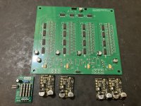
Just bought the balanced version of this, will be using Amanero USB so hopefully plain sailing. Stefano threw in a buffer / filter PCB in case of problems with Amanero.
Output will be discrete diamond buffers and may try Muses balanced volume from Meldano.
Output will be discrete diamond buffers and may try Muses balanced volume from Meldano.
Attachments


I'm tempted to also buy the balanced version to use with my Sowter I/V transformers and a DIR9001 usb-i2s iterface.
I see the output opamps are not fitted to yours which I also need as the transformers connect to the dac output directly.
Chiurutu, what are the direct ladder output levels and will they drive a transformer (low Z) input?
I see the output opamps are not fitted to yours which I also need as the transformers connect to the dac output directly.
Chiurutu, what are the direct ladder output levels and will they drive a transformer (low Z) input?
The value of the R=25K so this is the output resistance of DAC. This is quite high value and will be not sufficient to dive the transformers in low end among other issues. So the buffer for the low output resistance is needed. In all cases of load. This is simply very high output resistance...I'm tempted to also buy the balanced version to use with my Sowter I/V transformers
Higher than most of the SE stages tubes has...
Thanks Zoran and so no it isn't suitable for direct driving of the transformers so maybe two of my X10 clone tube buffers (200r Zout) will do the job if I keep the secondary load on the transformers as high as possible.
Maybe this 200ohms is too high for the solid state buffer? Please check that info?
That is almost exact value of buffer with catode folower with ECC88 tube? 🙂
...
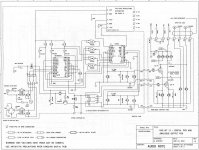
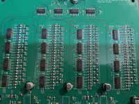
Actually this dac is 32 bit word converter. That is because all 4 x 8bit = 32bit shift registers '595 has R2R ladder network. With 24bit word rest 8bits (up to 32bits) are zeroes so there is no switching, but anyway 32bit going to conversion...
.
Voffset at the output of DAC at MSB point R2R ladder is typicaly 1/2 V+ of power supply. That will be 2.5V for 5V supply. So the buffers will ned a coupling capacitor. Value of this C depending on R at the input to ground...
.
More, my diskrete dac tested up to 384KHz sample rate doing well. Changing Fs samling rates in computer settings followed almost instaeniously converting and playing music. Without clicks or pops. There was a case ONLY with TDA1540 dac Any other dac was slower in these terms with same USB-I2S interface and computer. Among that these two dacs was converting 20KHz square wave into almost perfect analog 20KHz... All other - not.
So this dac probably will be the same.
That is almost exact value of buffer with catode folower with ECC88 tube? 🙂
...
Actually this dac is 32 bit word converter. That is because all 4 x 8bit = 32bit shift registers '595 has R2R ladder network. With 24bit word rest 8bits (up to 32bits) are zeroes so there is no switching, but anyway 32bit going to conversion...
.
Voffset at the output of DAC at MSB point R2R ladder is typicaly 1/2 V+ of power supply. That will be 2.5V for 5V supply. So the buffers will ned a coupling capacitor. Value of this C depending on R at the input to ground...
.
More, my diskrete dac tested up to 384KHz sample rate doing well. Changing Fs samling rates in computer settings followed almost instaeniously converting and playing music. Without clicks or pops. There was a case ONLY with TDA1540 dac Any other dac was slower in these terms with same USB-I2S interface and computer. Among that these two dacs was converting 20KHz square wave into almost perfect analog 20KHz... All other - not.
So this dac probably will be the same.
Last edited:
I was planning to not have a SS output and just connect the ladder output to the input of the X10 which is about 470k Zin through a .33 capacitor.
Output is 200R to drive the Sowters. One X10 pcb per channel. No gain but the Sowters provide this.
I built a second X10 using local components instead of the supplied Chinese ones. The performance at 1V RMS output into 3k load is slighty better at 0.015% THD at 1Khz compared to 0.019% using the Chinese parts.
Usefull on line tool for passive filter calculations
https://markimicrowave.com/technical-resources/tools/lc-filter-design-tool/
something like this

https://markimicrowave.com/technical-resources/tools/lc-filter-design-tool/
something like this
Check (measure or simulate) sowter Lp (primarry inductance) with Rsource of 200 ohms and see what is roll-off in the bass region... And phase too. Will be clear at first site...I was planning to not have a SS output and just connect the ladder output to the input of the X10 which is about 470k Zin through a .33 capacitor.
Output is 200R to drive the Sowters. One X10 pcb per channel. No gain but the Sowters provide this.
I built a second X10 using local components instead of the supplied Chinese ones. The performance at 1V RMS output into 3k load is slighty better at 0.015% THD at 1Khz compared to 0.019% using the Chinese parts.
With the X10 driving the transformer with the secondary loaded by the 22k input Z of my Behringer audio interface, the output drops to -20db at 30Hz.
Using a Picoscope instead, with a 47k load, the output is -3db at about 33Hz so I will either have to buffer the transformer output (preferably not) or connect to an amplfier with >47k input Z. Fortunately the NAD326bee I use as a preamp has 100k Zin.
Using a Picoscope instead, with a 47k load, the output is -3db at about 33Hz so I will either have to buffer the transformer output (preferably not) or connect to an amplfier with >47k input Z. Fortunately the NAD326bee I use as a preamp has 100k Zin.
Last edited:
You think better than TheWellAudio DAC_Lite? Seems doubtful....this one better than the other diy implementations out there...
https://www.thewellaudio.com/twsdac-lt/
Wouldn't be surprised if the dac of this thread is lower cost however, which could be a significant factor for many folks.
Last edited:
Only if the jitter is not random. Random jitter may show up as noise on an FFT measurement (because typical distortion measurement relies on Periodic Steady State spectral line spurs as an indication of distortion). However, random jitter may not sound like much like resistor noise. Indeed there are all kinds of random noise, as well as types of signal correlated noise....that should be able to be captured in a distortion measurement.
Different types of noise in part or in whole depend on their statistical bell curve tail properties:
https://www.edge.org/response-detail/11715
Last edited:
OK, maybe it shows up as noise. Well that is pretty easy to measure, is it not? So IMO jitter problems can be detected just be looking at the usual distortion and noise levels, which also tell you about distortion and noise. And since there are plenty of low cost DACs with very good HD+N levels, jitter doesn't seem to be a problem. I mean, if not, what am I missing here?
I still hold the position that jitter is a non-issue for current digital audio signals.
I still hold the position that jitter is a non-issue for current digital audio signals.
There is some info on how to measure correlated noise at: https://www.diyaudio.com/community/threads/phase-noise-in-ds-dacs.387862/#post-7063038Well that is pretty easy to measure, is it not?
For other types of noise it should show up on the noise floor, although in some cases that may also be correlated with signal or absence of signal. Smaller FFTs with fewer bins may be helpful to make noise floor changes more easily visible.
That said, the differences in noise shown in post #115 will all look identical on a typical FFT, since they are all of different types of white noise (white noise always has a flat frequency distribution). So you can't tell what the noise sounds like from looking at a typical FFT.
You have to buffer input to the transformer - primarry.With the X10 driving the transformer with the secondary loaded by the 22k input Z of my Behringer audio interface, the output drops to -20db at 30Hz.
Using a Picoscope instead, with a 47k load, the output is -3db at about 33Hz so I will either have to buffer the transformer output (preferably not) or connect to an amplfier with >47k input Z. Fortunately the NAD326bee I use as a preamp has 100k Zin.
DAC-filter-buffer-transformer
I tend to agree because no one has provided a convincing method of listening for it. Measurements are meaningless if you cannot actually hear it's effect.OK, maybe it shows up as noise. Well that is pretty easy to measure, is it not? So IMO jitter problems can be detected just be looking at the usual distortion and noise levels, which also tell you about distortion and noise. And since there are plenty of low cost DACs with very good HD+N levels, jitter doesn't seem to be a problem. I mean, if not, what am I missing here?
I still hold the position that jitter is a non-issue for current digital audio signals.
- Home
- Source & Line
- Digital Line Level
- Italian R2R ladder DAC, no CPID/DSP