In my opinion the filament in ac for dht is the best way to run.
Longer life, better sound.
Just to play with noise but it is the last problem.
In the pp separate the power of filaments is better, always.
And you can minimize the redsidual noise
Walter
Longer life, better sound.
Just to play with noise but it is the last problem.
In the pp separate the power of filaments is better, always.
And you can minimize the redsidual noise
Walter
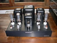
Attachments

Explain!novel?
What type of novel is?
Can you call it tube amplifier?
Only with simulation?
Built it, measure it then you can explain at the best if it will run properly
Walter
I don´t follow you here, I draw separate regulators, but I now included a common voltage source/raw DC. Better?:Not quite... you still need separate regulators, to prevent crosstalk between the antiphase PP halves.
But if the cathode resistor is shared (or zero) the Raw DC (rectifiers, caps, transformer) can be a single unit
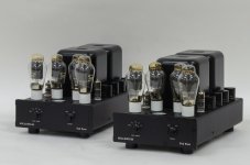
Attachments
Explain who?Explain!
I can’t
It is a circuit in a virtual world
Not real
I am not able
Only with real test lab is possible to discuss around it
Walter
Why do you bother to post, if you don´t understand 🙄?I can’t
It is a circuit in a virtual world
If you need help, I can explain to you. I´ll give you a clue: The anode transformer with the current sensing resistors in the center is the secret, as it acts as phase splitter and the sand parts balances the currents through it. I used LL1667 in the schematic, but Slagle will design the actual one.
Dave Slagle came with the original idea After that Rod Coleman helped adding the servo circuit and they both understand the circuit. Anyne who can read a schematic also will.
Read the thread below that is related to this subject, it might help you understand current balancing better.
https://www.diyaudio.com/community/threads/spud-schade-pp-anti-triode-ecl86.151220/
It is virtual
When you will build and test it will be a great start point
And use ac for filaments
The sound and the life of tubes are better
When you will build and test it will be a great start point
And use ac for filaments
The sound and the life of tubes are better
I don´t follow you here, I draw separate regulators, but I now included a common voltage source/raw DC. Better?:
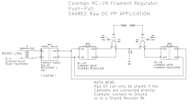
OK - Here's the recommended application circuit, for PP with a shared Raw DC, and single connexion to the cathode resistor.
BEWARE:
If you use a private cathode resistor for each DHT, the Raw DC cannt be shared!
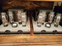
Attachments
Last edited:
Question:
How you can understand how much current is flowing in each DHT? At same - Vdc
They can be equal
Use separate winding ( one reversed in phase respect other) in ac and separate Rk
Or, in case separate ac winding, separate dc power and separate Rk
And a very well selection on tube (dynamic not only static)
Or, at least, negative grid regulation that is a minor issue if you can’t select the tube
Walter
Exactly as I thought, although I didn´t have a spice model of your regulator 😉 . The one I drew was ment to represent be the same but with simpler symbols. Thanks Rod!OK - Here's the recommended application circuit, for PP with a shared Raw DC, and single connexion to the cathode resistor.
Seems you didn´t read the last schematic, where it is shown that you measure over the primary OPT windings and then adjust for zero reading, if we assume the primary windings have the same series resistance(if not it is a simple task to calculate the expected voltage difference). By adjusting Rtrim this matter will be taken care of even if the driver tube drifts. In the design process it can be worth checking how the anode choke and the OPT primary currents interacts. Work in progress, designing must be in the virtual world, before building any listenable prototypes.How you can understand how much current is flowing in each DHT? At same - Vdc
They can be equal
Last edited:
Exactly as I thought, although I didn´t have a spice model of your regulator 😉 . The one I drew was ment to represent be the same but with simpler symbols. Thanks Rod!
Where is the last schematic?
I have seen the first one only.
Walter
Why do you bother to post, if you don´t understand 🙄?
If you need help, I can explain to you. I´ll give you a clue: The anode transformer with the current sensing resistors in the center is the secret, as it acts as phase splitter and the sand parts balances the currents through it. I used LL1667 in the schematic, but Slagle will design the actual one.
Dave Slagle came with the original idea After that Rod Coleman helped adding the servo circuit and they both understand the circuit. Anyne who can read a schematic also will.
Read the thread below that is related to this subject, it might help you understand current balancing better.
https://www.diyaudio.com/community/threads/spud-schade-pp-anti-triode-ecl86.151220/
I have seen the old thread.
After reading 5 pages without any prototype done by you I stop to spent time.
Did you built at the end the Ecl86 project or not? ( also in the proto form)
If yes can you show the results?
Thanks
Walter
#23. This is a screen dump of the *.asc:

Actually one can look upon it as a sofisticated DC version of the old Magnquest circuit:

Actually one can look upon it as a sofisticated DC version of the old Magnquest circuit:
Seems you are not enough into circuit designing, AFAIK Rod built it.I have seen the old thread.
After reading 5 pages without any prototype done by you I stop to spent time.
Did you built at the end the Ecl86 project or not? ( also in the proto form)
Download LTSpice, it will probably save you a lot of manual work building prototypes, once you get the hang of it.
Last edited:
#23. This is a screen dump of the *.asc:
View attachment 1247055
Actually one can look upon it as a sofisticated DC version of the old Magnquest circuit:
View attachment 1247060
Why some people make his life so difficult?
🤣
The Magnequest is much better even it has an inductor in input and it is parafeed.it as a sofisticated DC version of the old Magnquest circuit
More easy to build with good results related to the quality if irons ( as normally happen)
Let me to understand.
In old thread you propose a circuit and other built it?
And tested?
Walter
Hey Walter, why are you wasting your time here, only giving negative input? I have tried to help you, but you seem to lack understanding and also seems to be driven by emotions.Why some people make his life so difficult?
🤣
This is a technical discussion of ccs biasing of PP circuits, mainly addressed to Rod that now has given the asked for answers. So please find someone else to pick on.
If it is mainly addressed to Mr Rod why you don’t write him directly?
Reading the posts I suspect that there isn’t too much interested in this strange circuit that is forced to call it tube amplifier
It is not a negative notes I wrote
It seems that with the tool of simulation hundreds of engineers come out daily
Without any check in proto’s in the real world .
It seems that you haven’t did the same
Walter
Reading the posts I suspect that there isn’t too much interested in this strange circuit that is forced to call it tube amplifier
It is not a negative notes I wrote
It seems that with the tool of simulation hundreds of engineers come out daily
Without any check in proto’s in the real world .
Each project (as many other formers) I sent here is perfectly described, built and tested in form of proto and/or final stuffalso seems to be driven by emotions
It seems that you haven’t did the same
Walter
Last edited:
- Home
- Amplifiers
- Tubes / Valves
- PP with Rod Coleman CCS heater regulators