Sounds similar to some Cook Book magazines from not so distant past that published recipes without ever verifying the ingredients, quantity, cooking process or even tasting the final dish - a sure-shot recipe for disasterThen projects got published without the ELEKTOR staff building or testing any of these for verifying them working reliable
The tube amp had overall feedback from the output transformer. The elektor design had a loudspeaker coupling cap, probably of questionable quality.
Your use of a transistor CCS is actually a source of some thermal compensation, vs the Zener CCS.
appears to be some difference in ideas regarding the type of ccs used ie 2x diode, led, 2x bjt, zener
the current through R15 and R16 needs to be kept constant, the ccs setup needs to provide a thermally tracking current, not a constant current.
Attachments
Last edited:
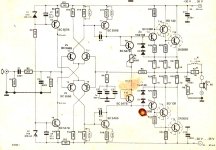
How do you get 0.6W in the 6k8 resistor? I get 0.2448W, if the total supply voltage is 70V how high is the zener current? First we lose 11,2V total over the zeners themselves we have 58.8V left, the current is limited by R8+R11+R12 that is 9800ohm resulting in 6mA. that results in 40.8V over R8 and 0.2448W. We lose a little more over R11 and R12 because of the 0.5mA going through then to the LTP but i ignore that. The zeners will dissipate 33,6mW.
The only components getting a bit toasty in this design is T7 T8, at 8mA and almost 34V over them that is 270mW or so in a TO92, I remember them getting a bit warm in my build.
You re right but even 0.2-0.24W is too much, the transistors used as CCS require something like 3uA in their bases, so it s useless to sink 5mA in the zeners, something like 1mA at most is more than enough.
As for T7/T8 they also sink way too much current, about 5-6mA, a 2mA value would be way enough since the output stage is the equivalent of a triple EF beta wise, so there s only a few dozen uA needed to drive it at full output power.
Since i ve already some comparables schematics from Elektor edited in my simulator i also did some sims with this one, as expected distorsion is low by the virtue of the high gain output stage and low overall gain to max out the NFB, but overall there s some basic improvements that could be done.
Hello Wahab
Would you be willing to share your improvements in the form of a schematic with values?
Would you be willing to share your improvements in the form of a schematic with values?

C2 is classic case of not very stable amplifier and making it too large.
C9 and C10 also made large so assume garbage slew rate.
Just raise R17 / R18 to 330 ohm to bring down the current
In sim all the tiny caps and large inductor wont make THD
anything great.
Doubt anything more than .1 to .03 % at 1k
Would have to make input/feedback caps large and bypass output
inductor to make a Sim produce any decent numbers.
And lower ridiculous large C2
so many arguments with these crutch caps. RF interference goes away with less than 47p
small cap over feedback might kill the overshoot, and slew rate would wake up lowering
C9/ 10
The higher gain Quasi Outputs and transistors as diodes for thermal tracking
is the neat thing about the amp.
Most people would just change it to complementary .....boring
and add typical VBE = oscillator
The Quasi might have strong 2nd harmonic distortion
Of course if you actually like TO3 quasi then getting rid of 2N3055
and use another TO3
Dont care about current source nonsense rather switching diodes or leds
5ma is usual current. Current sources/ Diff are kept low here at 500u
because anything higher amp is unstable. And Zeners are more thermally stable
and needed for symmetrical.
And looking at C9/C10 still not
very stable and made high to work. Needs one cap over the feedback.
Last edited:
I suppose you realized this is an implementation of the Peter Walker Quad 303 triples? Is the 303 known for having strong 2e harmonic distortion? Dunno: just asking.The Quasi might have strong 2nd harmonic distortion
Of course if you actually like TO3 quasi then getting rid of 2N3055
and use another TO3
Of course,once i got a in depth look at some parameters and a few time left, i ll explain what is to be avoided so people can design their own variants.Hello Wahab
Would you be willing to share your improvements in the form of a schematic with values?
As for your post about second harmonic it s should be known that quasi complementary stages produce lots of even harmonics but much few odd harmonics when it come to relatively high products.
Second harmonic higher amplitude than the rest is mainly due to design limitations, as is the third harmonic wich become dominant and of high amplitude at high power if the output stage beta is too low, that s why this amp has relatively low THD by the fact of its very high gain output stage.
Please check this out for an example !Hello Wahab
Would you be willing to share your improvements in the form of a schematic with values?
https://www.diyaudio.com/community/threads/awb50-a-simple-power-amp.155993/
I have built this amp from Elektor several times. Used with a regulated power supply and components as shown, it outperformed even a Cadence Valve amplifier among many others in the sonics department. It was not the most resolving as I realised later after building many other amplifiers. But at that time, it served very well. There was no instability at all.
I always thermally coupled transistors in this fashion - T1/T2, T3/T4, T7/T9 and T8/T10. T13 & T14 were mounted on the Output Stage Heatsink. Done this way, I never experienced any thermal drift.
A couple of times I used 2SC5200 in place of MJE3055 in which case setting bias was a bit touchy.
I always thermally coupled transistors in this fashion - T1/T2, T3/T4, T7/T9 and T8/T10. T13 & T14 were mounted on the Output Stage Heatsink. Done this way, I never experienced any thermal drift.
A couple of times I used 2SC5200 in place of MJE3055 in which case setting bias was a bit touchy.
Quasi is interesting,I suppose you realized this is an implementation of the Peter Walker Quad 303 triples? Is the 303 known for having strong 2e harmonic distortion? Dunno: just asking.
depends more on the input and more if differential.
Differential input/ feedback usually lowers the 2nd in a generic sense.
usually if you sim a complementary output than compare
to Quasi with no feedback / gain just the output follower. Then yes
technically the Quasi be slightly higher distortion.
But the higher amount adding to that usually
yes, higher 2nd harmonic.
But then add gain/ feedback 2nd goes down.
Far as the Quad, dont know. looking at the singleton
like input stage. Those can actually cancel and improve
distortion pretty well. And would guess the harmonic
profile be more common low distortion, but higher 3rd.
far as a guess
would it be ideal if the voltage across R15 an R16 is kept constant, regardless of temparature variations ?

- Home
- Amplifiers
- Solid State
- Found this old Elektor amp