Hi guys,
I have a Cambridge Audio Amp with swollen power/filter cap's. I had read somewhere that this is caused by reverse current when switching off. Adding protective diodes was recommended.
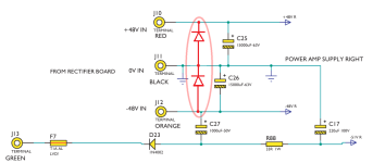
Am I adding these diodes (in red) correctly and are the 1n4007 suitable?
Thanks!
I have a Cambridge Audio Amp with swollen power/filter cap's. I had read somewhere that this is caused by reverse current when switching off. Adding protective diodes was recommended.
Am I adding these diodes (in red) correctly and are the 1n4007 suitable?
Thanks!
Attachments
The diodes won’t hurt anything - and 1N4007’s are fine and not really a bad idea for a number of reasons. But that’s probably NOT what caused the caps to fail.

The caps are bad, the aluminum is bulging.
I found the original text:
I found the original text:
Cambridge came back with a fix to replace blown 1000uf 50V caps and bypass them with a 1n Diode due to power down sequence reverse current and voltage spike blowing these little electrolytic caps.
Found out the unit has a flaw, rverse diode on power supply caps not included causes turn off voltage spike to blow caps on power supply board. Happens at 100-300 hours.
The atypical reason is time and the capacitor voltage rating being too close to the supply voltage , secondly bad positioning close to heat sources, and thirdly being subjected to any chance of reverse voltage. If the capacitors are damaged, discontinue use, and replace with same capacitance rating , but higher voltage tolerance. Example a 40 volt dual DC rail use 63v capacitor per rail ( not 50v types ) , a 50v dual rail use 80V ( not 63V )
50V caps are fine for 40V rails (in fact 40V caps are OK for 40V rails) - electrolytic caps use working voltage ratings, not absolute maximum. The lifetime specifications in datasheets assume running at 100% rated voltage. Increasing the rated voltage does extend life, but its a modest effect compared to running caps cooler or picking one with a 105C rating over one with a 95C rating. Using a cap at 50% of its rated voltage means using a cap that's 4 times the volume/weight/price, so its usually not an attractive proposition. Electrolytic cap size is proportional to capacitance times voltage-squared, as capacitor energy storage formula is 0.5 * C * V^2
I disagree, as a commercial sample example, Quads choice with 63v caps with 52V rails in the 405 , saw many thousands of users faced with choosing higher voltage types or babysitting their amps blowing bubbles at them atop the capacitor. Other factors though contributed such as the heat within the chassis, but higher voltage caps were in my experience the easiest and best solution.
All the 405 upgrade resources I can find specific 63V caps for the 405. Perhaps the original caps are failing, but that's likely heat and age.
Putting a higher voltage cap in there does nothing for you if it can’t handle the ripple current. That will cause heat and failure. Voltage by itself won’t. Junk brands are junk brands too so not everybody’s 50 volt (or 85C, or 2 amp) cap is made to the same standards. Look at rated life vs. ripple current. If you can’t find that information they don’t want you to know (Usually with good reason).
If it helps: I have always used 50V caps for my +/-42V rail Guitar/Bass amps since 1969 (do the Math), over 14000 amps so far.
Various brands along the way: originally Siemens (what today today is EPCOS), then regular "bread and butter" brands such as TRec , lately SunTan: never ever a problem.
30-40-50 y.o. caps sometimes show venting.
Important detail: my chassis are always well ventilated, >200W amps use fan cooling, which ventilate everything inside.
Airflow goes first towards Power Transformer and main filter caps 😎, then everywhere else, and exits chassis through slots above and below thick aluminum backpanel which is the main heatsink.
85C? ... 105C? .... nice to have those specs available, but inside my chassis you never ever have more than, say, 45C or so; anything above 50C means something is wrong and needs correction.
Meaning: I am a firm believer that Temperature is the main Electrolytic killer, and keeping them charged (meaning amp ON regularly) is the equivalent to "going to the Gym", meaning it keeps them well excercised and healthy.
New customers sometimes comment that "my amps are open" and that "you can see the wiring inside" ....which is true: both front and back panels have an end to end 8-10mm slot above and below, tolexed cabinet/shell is 15-20mm taller than what it "should".
So be it.
85C? ... 105C? .... nice to have those specs available, but inside my chassis you never ever have more than, say, 45C or so; anything above 50C means something is wrong and needs correction.
I think Mark's point is that at a given temperature well below 85 degrees Celsius, a capacitor specified to have 2000 h lifetime at 105 degrees Celsius usually has about four times the lifetime of a 2000 h, 85 degrees Celsius capacitor.
Which it is, the temp of a cap is inverse proportional to its life span.Meaning: I am a firm believer that Temperature is the main Electrolytic killer,
That being said, 105 degrees caps aren't that special and expensive anymore these days.
Although apparently enough to be saved on with most TV's these days.
I have replaced quite a few of those.
Exactly, yet I have replaced quite a few that were simple cheap 85 degrees ones.Well, TVs are usually HOT inside 🙂
Hi again guys,
It turned out that in addition to the filter capacitors, there was another problem +31 VDC offset. I took some measurements in what I think is the problem area (they are written in red)
The board looks good, no overheated areas. I measured all the capacitors with an ESR meter as they are in the circuit and they look fine. The final transistors are ОК.
I look forward to your advice.
Attachments

There circuit you've circled is a constant current source (CCS) and the voltages you noted are definitely problematic. There should be about 0.6V base to emitter at Q35, which should in turn drive Q34 to deliver about 0.6V across R23, i.e. constant current = 0.6V/150 ohm = 4mA.
At first glance, there's only 0.1V across R23, which might indicate Q34 collector has opened, or Beta deteriorated badly. But then how can there be 0.8V showing at Q35 base-emitter? Both transistors deserve scrutiny. I suggest connecting your meter's negative lead to the -35V rail and probing points of interest. The readings be easier to make and interpret.
Good luck!
- Home
- Amplifiers
- Solid State
- Protection diodes in the power supply