the path is from the center of the woofer to the center of the terminus opening - on the outside of the cabinet. So if the cabinet is a foot wide, and 2 feet front to back, the Path would be 3 feet for that drawing.
Just to clarify, the Hornresp combined response simulation model treats the two sound outputs as point sources, with the path length being the straight-line distance separating the two sources, as shown by the red line in the attachments. For the purpose of the exercise the cabinet does not exist.
Attachments

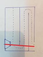

Understood - but if the cabinet was 1 foot deep in that drawing, the center of the woofer to the side of the cabinet would be 6", then it would be the length of the red line in Attach_2, and then another 6" to return on the back of the cabinet to the center of the terminus opening - I think? In other words it is the shortest possible path center to center on the outside of the cabinet.
then it would be the length of the red line in Attach_2, and then another 6" to return on the back of the cabinet
No, it is simply the length of the red line. As mentioned above, imagine that the cabinet does not exist and that there are just two point sources separated by the Path value. See the post linked below for further information:
https://www.diyaudio.com/community/threads/hornresp.119854/page-523#post-6069923
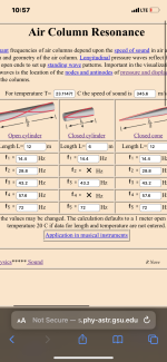
If it’s a subwoofer I wouldn’t care about creating a ’path‘ to remove the cancelation notch. I would want the driver and vent close toNo, the path is from the center of the woofer to the center of the terminus opening - on the outside of the cabinet. So if the cabinet is a foot wide, and 2 feet front to back, the Path would be 3 feet for that drawing. The Path is entered in the Cabinet section of the Wizard.
In order to know which is better, you need to dive into Hornresp and when you get the response close - draw a dimensioned drawing, to see what those dimensions require in order to be built. It may be that the woofer moves up the front of the cabinet if the length of the closed end needs to be shorter. Once you get a dimensioned cabinet drawing - feed those volumes and length back in to Hornresp and see how it works. If you need more volume with the same length, make the cabinet wider.
This process is a back and forth between a drawing of a buildable cabinet, and the Hornresp model. And with a dimensioned drawing, you can get the Path length you need to smooth the spikes and dips out of the response.
Attachments
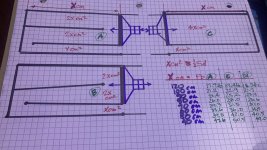
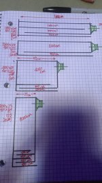
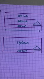
Look at all of these? apples to apples starting at 333/111cm2, then 666/111.. then ….
just keep the same box volume. Why bother with the generic ‘transmissionline’ concept when it’s just two simple air springs (one fold in between) you can manipulate better into a hybrid of sorts? And one without the extra resonances in the bandwidth?
the very last example in the drawing is silly 😝 it’s ignoring the other long dimension created ….(oops)
Attachments
Last edited:
Thank you all for your valuable input.
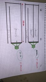
@Booger weldz: Thanks for the designs. I na ll the drawings, the driver is facing into the line. IS it a Hornloaded speaker?
How it differ from direct radiation systems.?
Also, suppose we have a wall behind the sub. Then having the vent opening toward the wall make any difference?
Thanks and regards,
Sumesh
It’s a subwoofer, load the backside with another resonator ? Kinda helps some of the saggy if needed
Attachments

Care to share the box design and XO diagram for this design?I have built a second design with a SB Acoustics 8" woofer that I like a lot better than the Dayton Audio. It has an F3 of 27Hz, in the version I built - and I have tweaked it down to 25Hz for the next time I build it. And I just started a standmount speaker using a 6" SB Acoustics, with an F3 of 33.2Hz.
I am selling the full build plans for the 6" SB Acoustics driver, on my website; if that's the speaker you are asking about. I have just built the Tower version of the speaker. It's fundamental frequency is ~28Hz, which is great. I now really appreciate the 6" driver for its midrange - which is incredibly clean in its upper response.
Okay, that speaker uses a Linaeum ET-6A tweeter that was made by Radio Shack - it is an amazing tweeter; but you have to buy them used. It has a much larger area than most tweeters and can be crossed over fairly low.
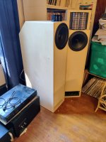
It's the speaker on the left. This is the 27Hz version - I have not built the 23Hz version.
It's the speaker on the left. This is the 27Hz version - I have not built the 23Hz version.
Attachments
If you are selling designs you are sharing at DIYAudio, you should post in the Marketplace instead.I am selling the full build plans for the 6" SB Acoustics driver, on my website; if that's the speaker you are asking about. I have just built the Tower version of the speaker. It's fundamental frequency is ~28Hz, which is great. I now really appreciate the 6" driver for its midrange - which is incredibly clean in its upper response.
I've been staring at these drawings for a few days now 🙂 The second drawing in the second picture is particularly intriguing; with that large chamber, would it be possible to mount the speaker into the 'side' of the enclosure, rather than at the end? I'm thinking that might be a cool design for a thin, on-wall speaker design.Look at all of these? apples to apples starting at 333/111cm2, then 666/111.. then ….
just keep the same box volume. Why bother with the generic ‘transmissionline’ concept when it’s just two simple air springs (one fold in between) you can manipulate better into a hybrid of sorts? And one without the extra resonances in the bandwidth?
the very last example in the drawing is silly 😝 it’s ignoring the other long dimension created ….(oops)
Also, do the pipes have to be folded to create the air spring effect, or could you have a centre chamber for the speaker, and then the pipe run in a concentric fashion?

@Booger weldz - thanks, I think I understand 🙂 So the goal is to have the folds of the tubes be where the pressure from the wave is the lowest?
I honestly DONT understand all the hype(?) about ‘standard’ transmission lines unless they’re honestly compared to the exact same box volume in other configurations (apples/apples) ??
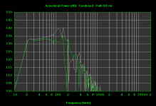
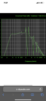
Why add the extra pipe resonance and offset driver position to help fix it(white graph verses green)
Why add the extra pipe resonance and offset driver position to help fix it(white graph verses green)
Attachments
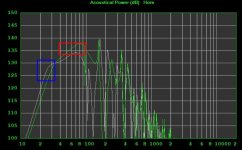
Similar example of same box volume but resonator shape usefullness ? The offset vent exit between closed ends(red area in box ‘A’ ) vs the nice deep subwoofer created in box ‘B’ (blue) ?
kinda interesting when apples to apples
kinda interesting when apples to apples
Attachments

- Home
- Loudspeakers
- Full Range
- An Improved Transmission Line Alignment