Chaps, It has occurred to me that with 2 small cuts and one additional short wire I can 'duel-rail' the ACP+ and power it with a Naim HiCap (or similar)
Has anyone done this? Did you achieve any perceivable improvement? I've a spare Avondale TPR4 that needs something to do 🙂
I've measured the std PSU brick and I got 23mV of noise - reduced to 0.1mV at the entry to the boards!! Given that result I can't imagine that a PSU upgrade will achieve much, but you never know until you try

Dual.
Expensive doesn't always mean better.
Exactly.
One thing worth considering, this cute little widget is universally lauded and excellent and making a genuine improvement. https://diyaudiostore.com/products/smps-dc-filter-p089zb-kit
I use them wherever they can fit and wholeheartedly recommend.
Expensive doesn't always mean better.
I've measured the std PSU brick and I got 23mV of noise - reduced to 0.1mV at the entry to the boards!! Given that result I can't imagine that a PSU upgrade will achieve much, but you never know until you try
Exactly.
One thing worth considering, this cute little widget is universally lauded and excellent and making a genuine improvement. https://diyaudiostore.com/products/smps-dc-filter-p089zb-kit
I use them wherever they can fit and wholeheartedly recommend.
My sentiments exactly. And +1 on the p089zb filter.If I had to choose between the two, I’d unquestionably and happily use ACP+ until I get old old and gray… but sometimes you really want what B1K brings.
Having build a number of both including variations with different parts and PSUs, I have to agree. The ACP+ is a very nice and quiet preamp especially if you switch the input coupling cap to something closer to 2uF down from the designed 10 (you'll get a far lower bass low end cut off). I've used mine to drive a variety of commercial and Pass DIY amps, and its currently my workshop's main preamp along with the latest AmpCamp mini. I love the sound of the "tube-y" B1K but dealing with the microphonics is a REAL PITA especially if you are using it with a power amplifier that has any decent amount of front-end gain. Look on the B1K thread to see the lengths to which one must go to avoid that, and even then YMMV. I'd imagine that a good pairing for that reason would be with an F4 which has nearly unity V_gain.
B1K + F4 requires some serious high efficiency speakers... 90db/w is not enough. Also, distortion of B1K increases dramatically with gain.
are these values correct?
Left side
R1 101
R2 76.3
R3 77
R4 125.2
R5 ~20
R7 33.24
R6 19.5
R9 1.5
R 10 1.01
R8 100
R11 100
R12 2.3
R13 7
R15 1
Right side
R1 1
R2 76
R3 76.7
R4 125.1
R5 22.5
R6 21.3
R7 33.2
R9 1.5
R10 1
R8 100
R11 100.5
R12 2.4
R13 7
Left side
R1 101
R2 76.3
R3 77
R4 125.2
R5 ~20
R7 33.24
R6 19.5
R9 1.5
R 10 1.01
R8 100
R11 100
R12 2.3
R13 7
R15 1
Right side
R1 1
R2 76
R3 76.7
R4 125.1
R5 22.5
R6 21.3
R7 33.2
R9 1.5
R10 1
R8 100
R11 100.5
R12 2.4
R13 7

Numbers are meaningless without their unit of measure, and an exact description of what you measured.
Did you measure the resistors and compare their values to the values on the PCB and schematic before installing them?
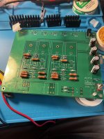
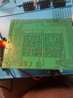
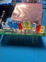
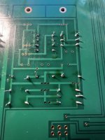
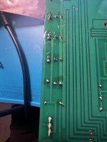
It's hard to tell from the underside of the board picture but some of the solder joints look lumpy, with possibly too much solder or not enough heat applied, or both.
Did you measure the resistors and compare their values to the values on the PCB and schematic before installing them?
It's hard to tell from the underside of the board picture but some of the solder joints look lumpy, with possibly too much solder or not enough heat applied, or both.
I'm not a soldering guru, but I'd second what @Ben Mah is saying about the solder joints. The ones I've circled in red here look like they might not have enough, and the one in orange there looks like it might be bridging the leads on that cap. A fair few of the others (not circled) look like they might be cold.
Don't despair though - see the one in green there? That's probably what you want to shoot for the others looking like. Anything dull or lumpy or oddly shaped, try to reflow it to look closer to that one.
If you tell us more about your soldering setup (type of solder, iron, the temp you have it at, dwell time, are you using rosin, do you have solder braid, flux, solder sucker, etc.) I'm sure the resident boffins can chime in with suggestions on how to dial in your technique for best results. 🙂
Attachments
Alright starting from the top since I barely put any effort into that post besides the values and some pictures, my bad!If you tell us more about your soldering setup (type of solder, iron, the temp you have it at, dwell time, are you using rosin, do you have solder braid, flux, solder sucker, etc.) I'm sure the resident boffins can chime in with suggestions on how to dial in your technique for best results. 🙂
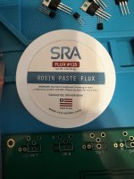
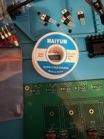
I have my solder at about 610 degrees. I use flux and the 63/37 I got from amazon.
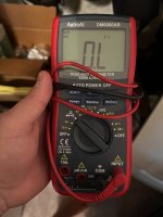
As far the values, those are after I soldered them, and I am not sure if the values are correct. The picture has the dial on the multimeter that I was using.
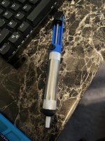
I have not used the plunger, but I might if I completely messed up.
As far as technique, i tried to have the tip of the solder pen on the lead hole, while the pen was making contact with the leads. The problem is that its super slow, I feel like I have to hold for more than 5 to 7 seconds before the solder starts to melt. Other times the solder starts to melt but it get stuck, so I put the pen over it and make a mess.
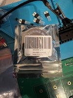
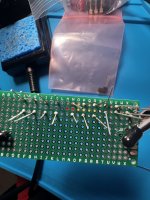
I got a little bit overly ambitious today, since I had free time and wanted to try and finish it today. Clearly my hubris got the best of me 😅
Attachments
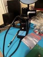

^ Most people don't consider it part of their 'soldering' set up, but I consider my magnification and illumination part of mine.
With modern phones, we can see everything re: a solder joint with a good picture. You should be able to inspect each of your solder joints equally as well as what you can see in the pictures above.
My
With modern phones, we can see everything re: a solder joint with a good picture. You should be able to inspect each of your solder joints equally as well as what you can see in the pictures above.
My
610 degrees Fahrenheit may be a bit low. Try 650 degrees. To solder, heat the iron to temperature, wipe the tip clean, apply a bit of solder to the iron tip, then hold the tip against the component lead and pcb pad, apply solder to the heated area and tip, keep the tip against the component lead and pcb pad until the solder flows into the joint. The solder flowing into the joint will be noticeable. You have rosin core solder so there is usually no need to apply flux to the joint prior to soldering. Wipe the soldering iron tip clean and apply a bit of solder to the tip before soldering the next joint.
As for the measurements, if you are measuring resistance include the unit of measure after the numerical value. The meter will show whether it is Ohm or kOhm.
As for the measurements, if you are measuring resistance include the unit of measure after the numerical value. The meter will show whether it is Ohm or kOhm.
I'd agree that 610 is too low. Personally I find 350C (662F) to be a decent enough temperature for PCBs, but I use a bigger tip than that. The thing is, a fine tip has two disadvantages - 1) it is harder to make solid contact with both pad and lead to transfer heat, and 2) it has less thermal mass to hold heat. What I mean by that is, imagine the tip is like a container you fill with heat - when you touch the tip to something, it transfers most of that heat to the other object to equalise the temps. The smaller your tip, the less heat you can transfer before the tip temperature bottoms out, leading to cold joints unless you dwell for ages and force the iron to heat everything while you sit there (by which time your rosin core will likely have cooked off). A bigger tip will lead to better temp stability, and should improve your dwell time problem. That's my understanding, anyway.
I've been using a 2.4mm chisel tip, but, assuming your iron allows you to try different tips, you should buy a few different kinds and find what works for you. Might also be worth getting another (more known quantity) brand of solder to compare results. Folks in the US seem to swear by Kester, but I've also had luck with the Multicore (Loctite) 63/37 stuff. Also, remember to clean the tip often, and tin the tip at the end of every session before turning the iron off.
Again, I'm not a solder guru, so, others may elaborate on or correct what I've said above.
I have a lamp above my setup and it provides decent illumination. But the phone idea is not bad either. Thanks for the recommendation!^ Most people don't consider it part of their 'soldering' set up, but I consider my magnification and illumination part of mine.
Ill definitely try higher temperature. I was soldering without making sure that the solder was going into the joint, leading to some of the resistors and caps to wiggle in the joint 😅Try 650 degrees. To solder, heat the iron to temperature, wipe the tip clean, apply a bit of solder to the iron tip, then hold the tip against the component lead and pcb pad, apply solder to the heated area and tip, keep the tip against the component lead and pcb pad until the solder flows into the joint.
Ill try this next time I get a chance and see.You have rosin core solder so there is usually no need to apply flux to the joint prior to soldering. Wipe the soldering iron tip clean and apply a bit of solder to the tip before soldering the next joint
Will do. I am still trying to get a hang of using the multimeter. Mine shows a k above the numbers.As for the measurements, if you are measuring resistance include the unit of measure after the numerical value. The meter will show whether it is Ohm or kOhm.
The kit came with a chisel tip, ill try that to see if it will work. Ill try 650 to 660 next time.Personally I find 350C (662F) to be a decent enough temperature for PCBs, but I use a bigger tip than that.
I saw the kester one on amazon, but it was a bit of a wait to get it, decided to use the one in the picture instead. Ill order some later and try.Might also be worth getting another (more known quantity) brand of solder to compare results. Folks in the US seem to swear by Kester, but I've also had luck with the Multicore (Loctite) 63/37 stuff. Also, remember to clean the tip often, and tin the tip at the end of every session before turning the iron off.
Gents thank you all for the tips!! This will help on my next session. Ill report back once I fix all my mistakes and post some pictures.
Tried the chisel tip 650 to 660 temp. Practicing on a junk pcb without flux. Works extremely well, now have to figure out how to clean up my previous mistakes on the acp+ board 😅. Thanks for all the help folks!Ill report back once I fix all my mistakes and post some pictures.
Attachments
Tried the chisel tip 650 to 660 temp. Practicing on a junk pcb without flux. Works extremely well, now have to figure out how to clean up my previous mistakes on the acp+ board 😅. Thanks for all the help folks!
Now that's looking more like it!
Desoldering is a bit of a skill, much like soldering (possibly more so), so maybe practice by desoldering those LEDs on that junk board before attacking the ACP+ board.
Word of warning, if you use the desoldering braid (probably the best tool for the job in the solder hasn't flowed all the way through the through hole) whatever you do, don't yank it if sticks to the joint. Pulling at it when it's stuck may result in pulling the pad clean off the board, which will ruin your day. Just reheat it by applying a tiny bit of solder to your iron tip and pressing it gently to the braid to get the heat transfer happening again, then lift it away gently.
I used the plunger on a couple and just reflowed the rest. Thoughts?Now that's looking more like it!
Attachments
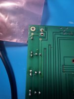

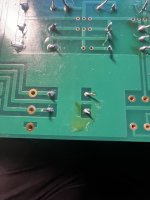
still not good enough.
you need to touch the solder pad and the component leg at the same time as well as applying solder to the spot.
that way the solder will flow around the leg and attach to the pad, takes 2-3 seconds at the most with the right tip at the right temperature.
use 60/40 or 60/37/3 solder, the latter one being lead/tin/copper, don't go fancy with lead free stuff
depending on the solder tip the right temperature will be 320 - 380 C
a good solder joint will look like a shiny cone completely covering the pad and the leg
the best practice regarding legs is to trim them before soldering, but if you trim later cut them at the top of the solder blob, do not leave them as they are in your photos
later if you re-flow the solder will cover the cut
- Home
- Amplifiers
- Pass Labs
- Amp Camp Pre+Headphone Amp - ACP+