Hello all! Earlier I posted about some static in the right channel I was getting. I thought I'd found the culprit in a cold solder joint on q5, but it returned. I then checked and resoldered any joint that looked possibly cold. Well, now I am getting ALMOST no signal on the right side. If I turn it all the way up, I get a very quiet signal on the right channel (I tested it with no signal to the left side to make sure it wasn't cross talk or something). This leads me to believe I have a damaged cap, maybe c3?
Before I start replacing caps and then active devices one by one, anyone got any ideas? When I test across DC1 with a DMM I am still getting the appropriate readings. Anything else I can test with a basic DMM that will give me any clues? I love this pre/HPA, but my construction skills seem to have kept it out of service more than I'd like!
Before I start replacing caps and then active devices one by one, anyone got any ideas? When I test across DC1 with a DMM I am still getting the appropriate readings. Anything else I can test with a basic DMM that will give me any clues? I love this pre/HPA, but my construction skills seem to have kept it out of service more than I'd like!
So it seems the idss of that particular part is quite low. While it seems most of j113 members bought have high-ish Idss, the j113 datasheet actually spec's the min Idss at 2mA. So it's not surprising to see a lower Idss part.

I've just got myself one of these and before I get too carried away I have a couple of questions.
1) Can I simply remove & bypass C1?
2) R2 and R3, do they absolutely need to be 150K, is there any wriggle room? Ie I've already got lots of 100K and greater values etc, etc.
Thanks 🙂
1) Can I simply remove & bypass C1?
2) R2 and R3, do they absolutely need to be 150K, is there any wriggle room? Ie I've already got lots of 100K and greater values etc, etc.
Thanks 🙂
1) As this uses a single supply and not a bipolar, removing C1 would connect your sources to approx 12VDC. If you like your source electronics, I’d strongly suggest you don’t try It.
2) 100K would work fine. If you have lots of various larger values perhaps you could parallel resistors and get something closer to 150K, though it’s not particularly critical
2) 100K would work fine. If you have lots of various larger values perhaps you could parallel resistors and get something closer to 150K, though it’s not particularly critical
Do you want low frequency performance at all? 0.22uF will have a cutoff frequency of ~60Hz. (And phase will start to get topsy-turvy much higher than 60) For full range performance, you’ll need to target a cutoff of around 5Hz or less, to insure that you have good phase margin in the lower frequencies.
However, reducing R2 R3 will require a larger cap, not smaller.
Assuming you can get close to 150K for those positions, 1uF will roll off at 13Hz, 2.2uF 5.5Hz, 3.3uF about 4Hz.
For what it’s worth, I have 2.2uF in my ACP+
However, reducing R2 R3 will require a larger cap, not smaller.
Assuming you can get close to 150K for those positions, 1uF will roll off at 13Hz, 2.2uF 5.5Hz, 3.3uF about 4Hz.
For what it’s worth, I have 2.2uF in my ACP+
The diyAudio Store headphone amp called "Noir", uses a 3.3uF film capacitor on the input and a 3300uF electrolytic capacitor on the output (in parallel with a 1.0uF film capacitor). But it wasn't designed by Nelson Pass.
No. That cap is 1000uF for a reason... the headphone resistance can be as low as 25 or 32 ohms, not hundreds of K.Assuming same applies to C3?
This means I'll need to think of something.
I'm just not going to accept a 1000uF Silmic 2 as my output coupling cap. I could delete the headphone section (I'll never use it), or just box it up and move it on.
I had intended to use it to drive my LuDEF instead of the Babelfish FE
I'm just not going to accept a 1000uF Silmic 2 as my output coupling cap. I could delete the headphone section (I'll never use it), or just box it up and move it on.
I had intended to use it to drive my LuDEF instead of the Babelfish FE
In your case, there's nothing much you can do... apart from asking Nelson to stop using single power supply rails... when he decides to release something new to the DIY audio community.
Edit: LuDEF also uses not only a coupling capacitor but the transformer as well... that might be okay with many, but I'd firmly decided to say no to caps and transformers in a signal path.
Edit: LuDEF also uses not only a coupling capacitor but the transformer as well... that might be okay with many, but I'd firmly decided to say no to caps and transformers in a signal path.
Last edited:
I'm just not going to accept a 1000uF Silmic 2 as my output coupling cap.
I don't understand what you mean by this. Can you explain?
I could delete the headphone section (I'll never use it),
The headphone section IS the circuit. You can’t delete it.
Can you explain?
same as you going to ditch brakes on your plane, well, they just make you going slower

The diyAudio Store headphone amp called "Noir", uses a 3.3uF film capacitor on the input and a 3300uF electrolytic capacitor on the output
Perhaps of greater significance: the diyAudio Store power amplifier called "Amp Camp Amp", designed by Nelson Pass, is rated to drive >4 Watts into an 8 ohm load. It has a 3300uF electrolytic capacitor on its output, in series between the amp and the 8 ohm load.
Of course headphones have much greater than 8 ohms impedance, and you'll drive headphones using much lower power than 4 watts, so perhaps an electrolytic capacitor in series isn't a performance limiter after all.
My ACP+ has been built with 1000uF Elna Silmic 2's. I've a strong allergy to Silmic II's, can't listen to them. Have now swapped them for some normal Elna caps.I don't understand what you mean by this. Can you explain?
The headphone section IS the circuit. You can’t delete it.
I meant remove the headphone jack and switch, not the circuit
Now we are talking! Thanks @WalterW 🙂
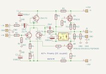
Guessing that in the above schematic the input cap is just there in case a power rail were to drop out (ie c3 could be removed).
I was also thinking that ideally the whole layout could do with having one of the boards mirror the other and using a 'horseshoe' / star type earth layout - basically copy the concept from a Naim Prefix.
I'd want single ended input too
...just some thoughts
Last edited:
But can you use the PCB as sold here?Maybe you should try to build it with a dual PSU. No need for the input and output capacitors. See pic.
Can you provide some guidance what needs to be changed to achieve that?
Of course one can assemble the whole thing on a vero board but not everyone is comfortable doing that.
- Home
- Amplifiers
- Pass Labs
- Amp Camp Pre+Headphone Amp - ACP+