Just "lazy" designing.....
LJM's CFP has no local decoupling of the driver , allowing for a local feedback loop (oscillator).
His EF2 designs also have no local decoupling , no base-stoppers.
He should read the Cordell and Self books , then sell projects.
OS
LJM's CFP has no local decoupling of the driver , allowing for a local feedback loop (oscillator).
His EF2 designs also have no local decoupling , no base-stoppers.
He should read the Cordell and Self books , then sell projects.
OS

From what I can tell the amp design is similar to my old Rotel amp which was considered a good amp and still sounds pretty good.
Right now I have biased it with 8-10 mV measured over one emitter resistor 0.1 ohm (80-100 mA) and I have power tested it with a 150w trafo +-42v supply and can sustain 34 volt RMS into 8 ohms with very low distortion.
With short signal burst's I get 40+ volt RMS into 8 ohms and low distortion.
It's been on for 24 hours now and frankly sounds and measures great on anything I can measure with my focusrite and REW up to 96khz. When I push it 2nd harmonics goes up a bit.
The only thing I would fault so far is the lack of instruction and flexibility getting the BIAS right with different rail voltages. The default 4.7kohm resistor is probably based on +-50v rail voltage, I now have 3.3kohm and +-40 volt rails at idle which would give enough BIAS to run distortion free with the rails sagging to maybe +-30 volts.
Given my experience with this the last few days I can't help think that the blown R28 was simply massive amounts of 3rd order harmonics as the rail voltages dropped when the amp was pushed creating a lot of HF energy, more than the 1-2 w resistor could take.
It will go into my 7.2 setup tonight replacing 2 NCORE 400 and I will do a bit of MADMAX and similar movies at very high volumes so we will see if it falls apart sonically and/or physically 🤔
hello all im new to this forum i need some help i just ordered the ljm l20se i wanted to know if i got the latest version and also if the one i got is legit.
https://www.ebay.com/itm/225000129429
thanks much
https://www.ebay.com/itm/225000129429
thanks much
There are many Chinese 'mall' sellers of these and they probably all come from the same source.
Maybe the components listed are genuine or maybe some are copies/fakes - you can never know.
Also, you will not get any technical support because the sellers have no technical expertise.
Worst case is that you've wasted $40 if ebay won't support a refund, or it blows your speakers.
I reecommend one of the loudspeaker protection boards sold on ebay to protect your speakers. eg
https://www.ebay.com/itm/18608440956
I use one on my Krell clone and it disconnects the speakers very quickly if there is too much DC or the output clips.
ya i figured as much its a shot in the dark with these kits i get the mx50 and it burned soon as i put a load on it the 10ohm resistor was burning up never did figure out why ..
Humm... those Toshiba Japan transistors in 2023? They sure look like fakes.hello all im new to this forum i need some help i just ordered the ljm l20se i wanted to know if i got the latest version and also if the one i got is legit.
https://www.ebay.com/itm/225000129429
thanks much
There are still 5200/1943 originals at Mouser.Humm... those Toshiba Japan transistors in 2023? They sure look like fakes.
The problem is that the Chinese persist using their fakes. If you really want that amplifier desolder everything and use original components. And be carefull when soldering - quality of boards is bad.
Here is the best one , the only one that uses decent parts .... and is actually designed right.There are many Chinese 'mall' sellers of these and they probably all come from the same source.
Maybe the components listed are genuine or maybe some are copies/fakes - you can never know.
Also, you will not get any technical support because the sellers have no technical expertise.
Worst case is that you've wasted $40 if ebay won't support a refund, or it blows your speakers.
I reecommend one of the loudspeaker protection boards sold on ebay to protect your speakers. eg
https://www.ebay.com/itm/18608440956
I use one on my Krell clone and it disconnects the speakers very quickly if there is too much DC or the output clips.
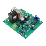
https://www.ebay.com/itm/17589468171
It even has the emitter resistor current overload input (5401/5551). China actually does manufacture the uPC1237 ,
they call it "C1237H" . THE Omron 16A relay is genuine .
OS
Attachments
So that's a speaker protection board not the l20Se amplifier the subject of this thread?
I'm not bothered about componenet quality on one as it's easy to test if it works. My Krell Clone pcbs use the same 1237 chip and it works well - cuts the output if it starts to clip.
I'm not bothered about componenet quality on one as it's easy to test if it works. My Krell Clone pcbs use the same 1237 chip and it works well - cuts the output if it starts to clip.
I've just got one of those kits in the mail, with Toshiba TTC5200 - TTA1943 which I can't discern yet if are true or fake. They are available locally through Farnell at a reasonable price, so if anything happens I'll buy some off a trusted retailer.
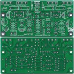
I've scanned the boards, and attached a pic with the bottom layer inverted for easier tracing if anyone wants a look at it.
I have a couple question for people who have built this kit. The resistor which sets bias in the schematic posted by Eliseu at the beginning of this thread is marked as a 9.1K, while on my board (and also on the components provided) is replaced by a 8.2k resistor. I've ran a preliminary simulation in multisim and that value would yield a bias current of just 3.4mA at a ±32V supply. Even at ±40V it would be just 5.5mA. Should I add another 1k and a 2k 10 turns trimpot and set bias to something more reasonable in the 10 to 40mA range? What current did sound best for you guys?
Another question on gain, the circuit as I've got should run at 28dB, which to me feels very high for any audio amplifier. I was considering replacing the resistor marked 330R near the 1000µF capacitor with something like 680R, which should lower the gain to a more reasonable 22dB. Any thoughts on this? Together with the lack of a DC blocking capacitor and any decent filtering on the input this amp feels to me a bit subsceptible to external disturbances.
I'm planning to run the amplifier off a 270VA 23-0-23 transformer, which should yield me a dc bus of ±32V. My speakers are 4 ohm (Indiana Line Tesi 261). Total max output power before distortion should be somewhere in the 85-90W per channel, which is a lot for the size of the room I've got.
I'll post some pics once I start building the boards and assemble the amp.
Attachments
Do see my notes on this design: LJM L20SE Design Notes
1. About Toshiba Transistors:
a) Today the Toshiba's included in most kits are fake.
b) If you have a reliable supplier, buy and use original Toshibas; Don't waste your time and resources trying to optimize fake components.
c) Remember that this kit needs large and efficient aluminium thermal sinks.
2. About the Q11/R17/R18/C8 biasing network:
The stated values work rather well. Lowering the R17 9.1K could be a signal that the seller does not trust the transistors he is selling.
3. About the amplification factor network R14, R15/C3 (10K, 330R/1000uF):
The stated values work rather well.
4. If you want to improve the design, perhaps to have better and cleaner transients, use better 80V C6, C7, C9, C10 capacitors (like United KZN) and parallel them with fast 100nF (like Wima MKP10); or to have a posher sink with 10V C3's by United KZN, Nichicon UKA, or Rubycon YXG; and, yes, a better 80V C2 by United KZN, or Nichicon UFG.
5. This kit has been optimized to work from a stable DC PSU of around 50V. I have been feeding it, for a long time, from a good quality 600W, 48V LLC SMPS without any problems.
Thank you for the useful information.
I've measured the HFE for all the power transistors I've got and it feels a bit sketchy.
TTC5200 NPN: 87 - 83 - 74 - 66
TTA1943 PNP: 124 - 126 - 127 - 131
especially the NPN ones do feel a bit off, the two at 74 and 66 are way off the minimum HFE of 80 stated in the data sheet.
I do have also two pairs of MJL21193/21194 available, which I am sure are original (bought them off a reatailer, ONsemi branded). If anything fails I might just use those. As i'm running below 80-90W output power at ±32V I should be able to get away with just two transistors per output stage, maximum power dissipation should be around 50W per stage or 25W per transistor at roughly 50-60% output power. The heatsink is fairly big, 250x80x60mm or 10x3.5x2.5". The amp is going to be mostly passively cooled but I do have the option to add a silent fan thermally controlled to boost dissipation if needed.
Tonight I'll apply a few of the suggestion in this thread in Multisim and get some data, hopefully in the weekend I'll start building the amp.
I only "optimized" the bias current to avoid excessive distortion with my initial somewhat limited 2x150VA +- 40VDC power supply. No detailed listening to potentially find a sweetspot.
It's now at 7mV over the 0.1ohm resistors which settles the temps at around 35-40 celcius after a few hours.
My amp has now been in use since my last post without any issues, the large cap in the feedback loop works very well btw. It effectively lowers the gain at DC to zero. I upgraded it with 2x250VA which ofc works a lot better.
I've done the mods/improvements suggested #4 above and It generally sounds pretty good but I have PS harmonic residues on the speaker output, very low level though it would indicate the power supply rejection is not as good as it could be. This probably explains why the amp does not sound as clean when pushed as my other amps.
To seriously improve the amp I believe a separate regulated supply for the VAS would make a big difference. I was planning this but did not want to dismantle the ones I have but seeing as you found a set of "clean" pcb's I might go ahead and order the same and re-work the pcb's to accommodate a regulated VAS supply.
Great if you can share where you got yours, PM me if you prefer.
See? If it walks like a duck, quacks like a duck and has feathers like a duck... it is a duck, it is not a Toshiba.I've measured the HFE for all the power transistors I've got and it feels a bit sketchy.
TTC5200 NPN: 87 - 83 - 74 - 66
TTA1943 PNP: 124 - 126 - 127 - 131
Regarding the usage of ONsemi and if I recall well, LJM does not recommend the usage of those with this kit. There is a newer kit (L20.9 ?) by him that has been designed to handle non Toshiba transistors.I do have also two pairs of MJL21193/21194 available, which I am sure are original (bought them off a reatailer, ONsemi branded).
Oh, it will fail, just remember to relay protect your speakers.If anything fails
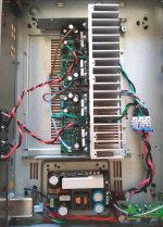
This heatsink will handle 2x125W RMS, at an ambient temperature of 25~30ºC without the need of a fan.The heatsink is fairly big, 250x80x60mm or 10x3.5x2.5".
It will be warm, but not much. You will be able to touch the heatsink.
I am using (see the attached image) the box and the heatsink from an Harman Kardon HK6500 that died long time ago.
Mind to leave space bellow the boards because the Wima MKP10 are bulky.
My L20SE, is feed directly from a DAC (~1,9V output) into a ALPS potentiometer and from there into the amplifier input.
Palying music at home throught a pair of fair speakers, with fair sensitivity, you will get plenty of dB from only 2x20W RMS.
I have this amplifier driving a pair of Dali Oberon 5 and the sound is very good indeed.
Attachments
I've bought the kit off Aliexpress, https://www.aliexpress.com/item/32878245872.html
At the time of purchase it was €34,48€, now it shows for €39,09 (taxes included to EU).
I've already got a relay protection board for the speakers, currently I'm using a very noisy tpa3255 chinese kit with quite a few issues. I want to go back to class AB as it's what I feel sounds best for a reasonable price.
I'll build the amp as is first, perhaps just adding a DC blocking cap on the input and the bias pots instead of a fixed resitor. Then, if I feel there's space for improvement, these are the things I'd like to do:
I've chosen a very "low" supply voltage on purpose, my speakers being 4 ohm are quite easy to drive. with ±32V on the DC rails I should be able to push almost 90W per channel without any appreciable distortion. The transformer is currently running on a 250V input tap, I do also have a 230V one that I could use in the future just in case I want the extra bit of power. I'd rather not do that tho, while my mains is rated at 230V, the real voltage is usually significantly higher. Still within regulatory limits, but I've seen easily 242 - 248V. Had I been running 8 ohm speakers I would have probably picked ±48V as well.
At the time of purchase it was €34,48€, now it shows for €39,09 (taxes included to EU).
I've already got a relay protection board for the speakers, currently I'm using a very noisy tpa3255 chinese kit with quite a few issues. I want to go back to class AB as it's what I feel sounds best for a reasonable price.
I'll build the amp as is first, perhaps just adding a DC blocking cap on the input and the bias pots instead of a fixed resitor. Then, if I feel there's space for improvement, these are the things I'd like to do:
- Lower Gain, chaning the 330R resistor to 560 or 680R (23.5 or 22 dB gain). Also add a 100nF cap in parallel with the 1000µ one in the feedback network.
- Add a 27/33pF in parallel with the 10k resistor from the output in the feedback network, to significantly lower gain at above audio high frequencies
- Add 3.3R base resistors to all A5200/C1943 power transistors
- Replace the 220µF bypass caps, add small MKP in parallel for better bypass at higher frequencies
- Add a 10R / 0.5µH series LR protection against capacitive loads on the output
- If needed add a small 2nd order RC input filter to cut down gain above 50KHz
I've chosen a very "low" supply voltage on purpose, my speakers being 4 ohm are quite easy to drive. with ±32V on the DC rails I should be able to push almost 90W per channel without any appreciable distortion. The transformer is currently running on a 250V input tap, I do also have a 230V one that I could use in the future just in case I want the extra bit of power. I'd rather not do that tho, while my mains is rated at 230V, the real voltage is usually significantly higher. Still within regulatory limits, but I've seen easily 242 - 248V. Had I been running 8 ohm speakers I would have probably picked ±48V as well.
Finally I've got some time to build the kit, took a couple hours to assemble everything and test it.


I've added only a few modifications. Besides the adjustable bias (2K trimmer and 470R in series with the "default" 8.2k resistor), I've swapped the miller capacitor for a 330pF instead of 100nF to increase overall stability. Feedback electrolytics got a bit banged in shipping, I've used instead some nichicon I had laying around plus a 68nF MKP cap soldered in parallel below the board. All "main" 220µF electrolytics have been bypassed with 100nF x7r ceramics. For the time being I've left the rest of the feedback loop default (10k / 330R)
I've set the bias to 20mA, the amps do work very well, output dc bias is almost non-existent (2-3mV). I've been powering them with a ±32V from the toroidal I mentioned in the last post. An early listening test into some small JVC speakers I had laying around did sound absolutely promising, can't wait to fit everything in a proper case and run this amp with a decent source and my indiana line speakers.
I've built the amplifier, managed to fit everything in a 42x22x12cm box (LxPxH). Just assembled it, still waiting to apply a proper finish and perhaps a different material (aluminum / steel) face plate.
So far the sound quality is very good, the gain originally was set too high and a fair bit of external noise was picked up, I've toned it down from 28-ish dB to around 22 replacing the 330R resistor in the feedback network with a 680R, making it much more manageable. I've got also a 50k multi-step pot on the input, while being a fake "alps" from aliexpress it does actually do its job well. While I was assembling it, I've also added LR filters against capacitive loads on the output stages (10R + 0.6µH) and input dc blocking capacitors.
Besides the main amplifier supply (±32V), I've got a dedicated 5V line to power up an external DAC, avoiding any issue with ground loops or noise being picked up from elsewhere. Rather than using just a 7805 on a 32-35V input, I've used first a LM2596 board to rough down the voltage to 8.5V then the 7805 to provide a low noise supply without too much power dissipation. The protection circuit runs on its own 16V transformer. I could have used a smaller one but that was the only hone I had around with the right voltage.
Most of the space inside the box is taken by the transformer and the board with the smoothing caps, I could have probably managed to squeeze things a little more by moving the amplifier stages to one side and the toroidal on the other, but I've decided to keep things as is. I've got a fair bit of space on my desk, and as this is going to be a daily driver for PC sound, it does fit well below my main screen without being too large. I've left some space near the input for possibly integrating the DAC or some other input stage in the future.
I'll post some more pics once I've applied some finish to it and perhaps found a better material for the front panel itself.
In this case, you have lowered the frequency pole by 3.3 times. Pole is the frequency at which the amplifier's output impedance begins to increase. In this amplifier, the Miller correction has a capacitance of 100 pF, so the pole is in the low frequency region, approximately 50 Hz (I will clarify later). With a capacitance of 330 pF, the pole will decrease to 15 Hz, which will reduce the quality control of the woofers in the region of resonant frequencies. And where is the stability?I've swapped the miller capacitor for a 330pF instead of 100nF to increase overall stability.
All "main" 220µF electrolytics have been bypassed with 100nF x7r ceramics.
I don’t understand why this is being done, and most importantly, who is this, what does he teach?
Ok, let's calculate, if the standard DAC output is 1.5 volts RMS, this is about 2 volts of amplitude voltage at the amplifier input, with a coefficient of 10k/680 = 14.7, we get 2 * 14.7 = 29.4 volts of swing, with a power supply of +/-32 volts, your distortion will drown out the sound faster than the signal amplitude reaches its maximum. Instead of 680 ohms, you can safely set it to 1 kOhm.So far the sound quality is very good, the gain originally was set too high and a fair bit of external noise was picked up, I've toned it down from 28-ish dB to around 22 replacing the 330R resistor in the feedback network with a 680R, making it much more manageable.
I've got also a 50k multi-step pot on the input, while being a fake "alps"
Fake Alps is not the worst thing, the fact is that the input impedance this amateur amplifier is only 10 kOhm versus 50 kOhm of the volume control, which means that when adjusting the volume, the cutoff frequency will be synchronously adjusted. The input RC filter in the amplifier is limited to 220 kHz, setting the volume control to less than half will reduce this frequency by 10 times, i.e. up to 22 kHz, which is not enough for high-quality sound reproduction because the cutoff frequency is less than an octave to the cutoff frequency range.
P.S. In any case, I still want to congratulate you on putting together a working project. It’s great when a person assembles it with his own hands - and it all works. I hope in the future you will be able to select for implementation a higher-quality ready-made power amplifier unit in which there will be no ridiculous and illiterate circuit layout solutions, in which the author himself could not explain the logic of his plan.
Last edited:
- Home
- Amplifiers
- Solid State
- Power Amplifier LJM L20SE