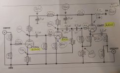
Hi, I mapped the schematic of this preamp with my resistor values.
Many, those made in carbon, have quite different values from each other.
I would like to replace them all with good new Kiwame ones. I think I'll leave the Dales.
I detected all the HT tensions. The filaments run at 12.6Vdc (lm317 to3). On the secondary of the filaments I have 14.5Vac.
I need to drive a 5K load on it. I think I will have to increase the capacity of the mkt capacitor (currently 6.8uF) at the output.
According to my calculations it takes 16uF for a high pass at 2Hz. I would also like to change the blue mkt caps and red mkp wimas for good audio grade mkp's.
I don't know if you have done this very interesting reading: https://ttradio.net/clone-marantz-7-m7-line-amp/
As you can see from my current diagram I don't have the correct values of the blue mkt capacitors.
The advice I ask you would be:
I don't know how much current the transformer can provide. Currently, with a total load of 10mA it's just timidly lukewarm, but maybe that's not saying much. There is a 6c4p-ev rectifier valve which I believe can carry, maximum, 75mA.
...and then there's the feedback....will it be a good thing implemented with those values?
Thanks for any help/advice!
Many, those made in carbon, have quite different values from each other.
I would like to replace them all with good new Kiwame ones. I think I'll leave the Dales.
I detected all the HT tensions. The filaments run at 12.6Vdc (lm317 to3). On the secondary of the filaments I have 14.5Vac.
I need to drive a 5K load on it. I think I will have to increase the capacity of the mkt capacitor (currently 6.8uF) at the output.
According to my calculations it takes 16uF for a high pass at 2Hz. I would also like to change the blue mkt caps and red mkp wimas for good audio grade mkp's.
I don't know if you have done this very interesting reading: https://ttradio.net/clone-marantz-7-m7-line-amp/
As you can see from my current diagram I don't have the correct values of the blue mkt capacitors.
The advice I ask you would be:
- What values should I use for the blue mkt capacitors but also for the red wima capacitors?
- Are the currents of the first two stages correct?
- How can I modify the cathode follower (currently with ecc82) to be able to drive 5k of load, other than increasing the capacitance of the output capacitor? Higher current? How much? I have ecc81, ecc88, 5814, 5965, 6211 available in my drawers. Taller valves don't physically fit and I wouldn't want to cut the cover.
I don't know how much current the transformer can provide. Currently, with a total load of 10mA it's just timidly lukewarm, but maybe that's not saying much. There is a 6c4p-ev rectifier valve which I believe can carry, maximum, 75mA.
...and then there's the feedback....will it be a good thing implemented with those values?
Thanks for any help/advice!
Attachments


5k is a very low load to expect a 12AU7 to drive, and there isn't much you can do to increase drive without compromising performance, as even best case you'll only get ~500 ohms of output impedance. Even modifying the circuit to something like a 6DJ8/ECC88/6922 etc will not be ideal, as 5k is a tough load for a smaller triode to drive without excessive distortion.

Thanks for your answer. Unfortunately, unless I cut off the lid, and assuming that the transformer can provide HT current and extra current for the filaments, I cannot use tubes with 6cg7, 12cg7, 6n6p (with adapter), 12bh7... ..etc.. . 🙁
However, I would like to start doing a test on the ecc82, I think it is enough to put a resistor in parallel to the 10k current to increase the current. How far can I go with the ecc82 in terms of current? So I'll also test the transformer....in the meantime.... Thanks
However, I would like to start doing a test on the ecc82, I think it is enough to put a resistor in parallel to the 10k current to increase the current. How far can I go with the ecc82 in terms of current? So I'll also test the transformer....in the meantime.... Thanks
Thanks for the reply, unfortunately I have a class D amplifier with 5k input impedance.It is not enough to put any resistor in parallel to increase the current. That will only make everything even worse. The problem is the 12AU7, not the resistances.
I don't know what the shunt across the output pot is for either.
I may as well give up on using it. I also have another one with 20k input impedance (QSC).
Can I do anything for 20k entry fee?
To me this 12au7 seems polarized with little current, from the readings I have done on this forum.
It doesn't seem to me to be at its maximum expression of low output impedance.
Question: can't I drive 5k even with an ecc88?
Thank you
(shunt across the output pot is for either It's the least of my problems. I can delete it in 1.5 seconds if it makes no sense to exist)
Tubes are high impedance devices. Even the 20k amplifier would be a strain for the cathode follower,
and will increase its distortion. But it would certainly be a better load than the 5k amplifier.
But the 100k pot is incompatible with either load. You could relocate the pot to the input instead.
and will increase its distortion. But it would certainly be a better load than the 5k amplifier.
But the 100k pot is incompatible with either load. You could relocate the pot to the input instead.
I apologize.
The 100k potentiometer is already input. I just took an almost identical online diagram, and made my own values and a couple of other corrections.
The diagram represents my preamp exactly, except the pot!
I hadn't noticed that the pot was coming out.
I corrected it, sorry.
I would like to use the pre at least with this 20k input amplifier. Possibile che non riesca a migliorare lo stato attuale delle cose riguardo la CF per poter pilotare carchi bassi, in questo caso 20k ? Grazie
Attachments
That's a generalisation I don't agree with.Tubes are high impedance devices. Even the 20k amplifier would be a strain for the cathode follower,
and will increase its distortion. But it would certainly be a better load than the 5k amplifier.
But the 100k pot is incompatible with either load. You could relocate the pot to the input instead.
Maybe it applies to the Marantz design but I have done much testing on my Musical Fidelity X10 buffer with a variety of tubes drivinga 4k7 load (because my Naim IXO crossover input impedance can go this low).
I've tried 6P1, 6N11 and currently using PCC88 with a 10k anode load on the outut triode and distortion is below well below 0.1% at 3v RMS at 10kHz with B of 70v. (+-35)
To the OP, test your Marantz using REW etc because it may perform acceptably.
Thanks for your answer. I only need 1/1.2Vrms of output to drive my amplifiers at maximum power, whatever they are. And I will never reach that power, I live in an apartment not on the moon.
I'm not able to do what you say with REW, unfortunately.
I would just like to optimize my preamp (also) for the lowest output impedance, be it with the ecc82...88..81..or others that I can get, those that can physically fit inside it (height problems).
I don't think the current CF setup is for minimum output impedance. I'm sure.
I wanted to do this on the occasion of replacing all the resistant ones that have too high a tolerance and in any case are too different from each other. Just as I wrote in the initial post.
Thank you
Please read Merlin's page on cathode followers, especially the comment about low output impedance.
http://www.valvewizard.co.uk/accf.html
http://www.valvewizard.co.uk/accf.html
My condolences... 🙂... unfortunately I have a class D amplifier with 5k input impedance....
But then again, you may have gain to burn, and, at least as a temporary measure, you may try to insert a 10-20K resistor in series with the output to ease the load on the ECC82.
Or you may want to try to bypass the preamp all together. I run the outputs of my Gustard DAC straight into my power amp.
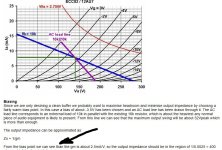
THANKS. ..on this nice internet page you can see that an 8mA ecc82 current produces a zout of 400ohm.Please read Merlin's page on cathode followers, especially the comment about low output impedance.
http://www.valvewizard.co.uk/accf.html
In my case it is 4.1mA. I'd like to know what the current zout is. I don't know how to understand it.
Wizard, in reference to the graph (which I attach) says: "From the bias point we can see than the gm is about 2.5mA/V".
I don't see any 2.5. But where should I look? 🙁
But wasn't there a rule that said that the zout must be 10 times lower than the load? Maybe I'm confused.
thanks
Attachments
Also remove the 10k series resistor at the output, unless you must use the 5k amplifier.
In that case with the 10k present, the gain will drop to around 1/3 that of no load.
Yes, the cathode follower small signal output impedance is ~1/gm, but its distortion will rise
if loaded by anywhere near that. A factor of 5 to 10 lighter load than zout is more suitable.
Low output impedance does not mean low distortion under heavy loads (on the order of 1/gm).
Last edited:
It's a shame you cannot conduct some measurements because how will you know what any changes are good or not so good.THANKS. ..on this nice internet page you can see that an 8mA ecc82 current produces a zout of 400ohm.
In my case it is 4.1mA. I'd like to know what the current zout is. I don't know how to understand it.
Wizard, in reference to the graph (which I attach) says: "From the bias point we can see than the gm is about 2.5mA/V".
I don't see any 2.5. But where should I look? 🙁
But wasn't there a rule that said that the zout must be 10 times lower than the load? Maybe I'm confused.
thanks
I feel that a 5k load is not too low but the 10k after the 6.8uf should be removed to avoid attenuation of the output.
Have you tried listening tests with it unmodified?
I would like to be honest.
I thought certain changes were quite "standardized" and obvious.
For example...a 12ax7 like CF is known to be a pain. Well, I was thinking something similar.
I thought that an ecc82 like CF and perhaps with 8/10mA of current was at its minimum output impedance, regardless of measurements.
Now 4mA flows through it. After the tons of hours I spent on this site reading (with great pleasure) it seemed obvious to me that 4mA through an ecc82 was not enough to drive a low load, regardless of whether it is 5-10-20 or 25k.
For example, a 6n6p is known to be fine with a minimum of 10mA of current. This is just another example.
I read that ecc82 are not very popular here on the forum. Which distort quite a bit and things like that... and that an ecc88 would be better, in a condition like mine.
I also read that the ecc82 should be "used hot" = current.
I'm not capable of measuring well, perhaps I don't have great tools.
I don't know how to do it well. English is not my language, I apologize for any errors, it's not easy!
I have listened to this preamp and I know how it sounds but I have listened to it in another setup. now they are in the process of changing with other needs.
For example: The 10k R outgoing should be removed because it lowers the level. The fact that I don't even need that high a level that much.
If the R is good for driving low loads... I would leave it. I don't need all this gain, actually, but I can easily live with it. I have the volume!
The fact is that there is a serious need to change the resistors because they are "out of range" (see my initial post)... and while I have dismantled everything I would have liked to do the other things too. Even the interstage capacitors are of incorrect values according to what they should be. Ok, I won't dwell on it. Maybe you didn't read my initial post. Needless to repeat here writing 1000 words. I'm sorry.
I would have liked to receive an example advice:
The best you can do is put an ecc88 in it and polarize it with "X mA".
Use an R of "X kohm". Remember that the 88 has 6.3v filaments! If you don't succeed with 88, leave 82 and polarize it like this.... etc etc..
Let us know how it goes!
You can't do better than that with that diagram or with the valves!
good night 🙂
Last edited:
You have a need to change them where out of spec., but not to change their values willy-nilly as you have done. Stick to the Marantz values.The fact is that there is a serious need to change the resistors because they are "out of range" (see my initial post)
THANK YOU. I WOULD LIKE TO CHANGE THE RESISTORS BECAUSE, PERHAPS, DUE TO OLD AGE, THEY ARE QUITE DIFFERENT IN THE TWO CHANNELS WHICH ALSO GENERATE DIFFERENT VOLTAGES IN THE VARIOUS TEST POINTS. THE VALVES ARE NEW AND MATCH IDENTICAL WITH AMPLITREX AT1000. IN ADDITION, SOME DO NOT SEEM LIKE THE REAL ORIGINAL MARANTZ VALUES. There are so many schemes around that I'm not even sure of the exact values they should be. Apologies for the capital letters.You have a need to change them where out of spec., but not to change their values willy-nilly as you have done. Stick to the Marantz values.
At the moment I haven't changed any resistors. It's exactly like when I bought it.
- Home
- Amplifiers
- Tubes / Valves
- UPGRADE Cathode Follower and other mod - Music Angel Marantz 7 Clone