Thank starcat,
I always put pots (2 or 4 ch) in my headphone amps as I don't use any digital sources other than a CD player. I guess that does have a volume control (Resolution Audio Opus 21), but I don't use it (see Webster: Neanderthal). I'll try things with the relays in, and see how it goes. Hopefully I won't select bypass and output to the power amp 🙂 My wife might be startled.
I always put pots (2 or 4 ch) in my headphone amps as I don't use any digital sources other than a CD player. I guess that does have a volume control (Resolution Audio Opus 21), but I don't use it (see Webster: Neanderthal). I'll try things with the relays in, and see how it goes. Hopefully I won't select bypass and output to the power amp 🙂 My wife might be startled.
Hello guys,
I have for sale the blowtorch clone and a few empty pcbs that can be used to build one but also a few spare pcbs to build an Iron Pre.
https://www.diyaudio.com/community/threads/blowtorch-gain-stage-and-pcbs.399877/#post-7365879
https://www.diyaudio.com/community/threads/iron-pre-pcbs.399878/#post-7365881
Hello Hicoco,Eric could you confirm all the powers supply we exactly need please?
That is what i found in HCFR Forum:Rechercher - Page 2
Sorry in French...Eric you wrote on 27 Oct 2015.
"Voici:
Carte preamp:
entre +/-18v min et +/-35v max redressé ou +/-24v régulé (attention en version +/24v il faut prévoir une alim additionnelle type UGS simple non prévu dans la CG en cours)
+5v pour les relais
Carte MCU:
+6v (il est sans doute envisageable d'alimenter directement en 5v en bypassant le(s) LDO(s) 5V sur la carte - non testé)"
also that is the link for the gerber for the old UGS AI and UGS simple
alims ugs.rar - Petit Fichier
I know this is an aging thread, and I'm currently in the process of reviving may failed attempt to build this pre back during covid. I never got past the shunt PCBs. I'm getting some help from @schultzsch to help me sort out the problem(s). My question; What trannies and secondary voltage did you use on yours? You did build this pre? Any advice? AT the time I used I bought the Hammond, 229D56, 229D16
Thx,
Rick
Your 28vac trafos are just fine.
You need to set the shunts for 24vdc. Higher voltage drop across the ccs mosfet means better performance but also a bit more heat.
The ugs modules can be powered up directly from the shunts with 24vdc or from the onboard ldos depending on how you populate some of the ferite beads.
I guess you will power up the modules directly from the shunt regs.
Attachments


Yes, agree. Thanks for the illustration too.Your 28vac trafos are just fine.
You need to set the shunts for 24vdc. Higher voltage drop across the ccs mosfet means better performance but also a bit more heat.
The ugs modules can be powered up directly from the shunts with 24vdc or from the onboard ldos depending on how you populate some of the ferite beads.
I guess you will power up the modules directly from the shunt regs.
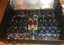
@Ine, thanks for sharing your PSU. Those Toroidys' and your whole layout looks very professional. 🙂
Hello @Ine and @Alex_twn, nice to see you around!
Me… I prefer the better performance at the expense of some extra heat.
Edit. If you have 28vac secondaries you can always insert some resistors between the secondary and the bridge lowering easily the dc voltage after the bridge. Well this if you can’t manage the extra heat.
If you use snubbers on the secondaries you will have to calculate them with the resistors connected.
not only ok but better. I ran a sim showing how the regulator works from 30 to 35vdc on the input and 24.7vdc on the output.more is also ok
Me… I prefer the better performance at the expense of some extra heat.
Edit. If you have 28vac secondaries you can always insert some resistors between the secondary and the bridge lowering easily the dc voltage after the bridge. Well this if you can’t manage the extra heat.
If you use snubbers on the secondaries you will have to calculate them with the resistors connected.
Attachments

Last edited:
Back to working on the two I am building. Almost have the preamp boards done (just the relays and psu jumpers to add). uC boards are done and loaded with latest firmware. I have one shunt PSU built, have the parts for the other 3.
I built one of Eric D's power supply boards yesterday and hooked it up to one of my trannys (Toroidy 100VA 4x24 2x8V). The unloaded voltages I am seeing are a bit high, but I guess not unexpected. I'm seeing ~35Vdc for the 24V supplies and around 11Vdc (closer to 12) for the digital feeds. I guess I'll just need to anticipate dealing with some extra heat.
I built one of Eric D's power supply boards yesterday and hooked it up to one of my trannys (Toroidy 100VA 4x24 2x8V). The unloaded voltages I am seeing are a bit high, but I guess not unexpected. I'm seeing ~35Vdc for the 24V supplies and around 11Vdc (closer to 12) for the digital feeds. I guess I'll just need to anticipate dealing with some extra heat.
Yes it might heat a bit. When you load the power supply board with the preamp you should see the supplies dropping a bit to maybe around 32v.
On my side I am finally completing at the moment the UGSD (after 0 DIY for more than a year).
More about this design soon.
On my side I am finally completing at the moment the UGSD (after 0 DIY for more than a year).
More about this design soon.
I am in the same boat...my build from Covid times is stalled. I moved and it sits in a box. I really do need to dig it out...Hello Hicoco,
I know this is an aging thread, and I'm currently in the process of reviving may failed attempt to build this pre back during covid. I never got past the shunt PCBs. I'm getting some help from @schultzsch to help me sort out the problem(s). My question; What trannies and secondary voltage did you use on yours? You did build this pre? Any advice? AT the time I used I bought the Hammond, 229D56, 229D16
Thx,
Rick
Question re: heatsinks for the shunts: are the onboard heatsinks sufficient for these, or do most people sink the mosfets to the case bottom? I was thinking of ordering some Aavid 530002B02500G screw in 2.5" heatsinks instead of the Ohmite ones specified.
Also, @Alex_twn , you were spot on your guess of 32V; with one shunt connected with the 470R load resistors, that is what it dropped to.
Also, @Alex_twn , you were spot on your guess of 32V; with one shunt connected with the 470R load resistors, that is what it dropped to.
Agreed Alex. I questioned my ability to properly drill the chassis base plate for mounting the shunt devices to it, so am going with the onboard heatsinks. I had wanted to use the Aavid bolt on version, but it appears those are only available in 1.5", so I went with the solder pin 2.5" above.
Got all 4 shunts built, adjusted, and tested. I was kind of surprised that the 470R load resistors run that hot (85-92* C) as there isn't much current thru them (~51mA, so about 1.22 W on a 4W resistor).
Got all 4 shunts built, adjusted, and tested. I was kind of surprised that the 470R load resistors run that hot (85-92* C) as there isn't much current thru them (~51mA, so about 1.22 W on a 4W resistor).
Hello All,
Sorry for my English ...
I will use 4 salas ultrabib for +/-24V for ugs modules and 4 jung super regulators for +/- 15V for muses 72320.
I would like the salas regulators to be turned on when the preamplifier is turned on or when coming trigger input signal, and to be turned off in standby mode. I don't like that when the preamplifier is in standby mode it gives heat continuously 24/7. Has anyone thought about this? Are there problems with working only +5V, + 6V (maybe and +/- 15V for muses chips). Can salas ultrabib to be turned on by relays only when there is an input signal (trigger in) or when the preamplifier is turn on by the remote?
Is it a problem with the input signals to the Muses72320 if it is not powered by -/+ 15V? Possibly, it can only be powered with 3V3 (pin17).
Actually this is what I did on the UGSD, I implemented this feature on the main power supply and I am switching off directly at the main the unused transformers (mainly the ultrabib).
It should be possible as well on the UGS muse but need to find the right method to control the ON/OFF of the power supply.
Here is the link on the new UGSD btw, as I explained that I will share when ready
It should be possible as well on the UGS muse but need to find the right method to control the ON/OFF of the power supply.
Here is the link on the new UGSD btw, as I explained that I will share when ready
Are you using the UGS Muse board set from Alex (from the group buy). The preamp boards take the +/-24V from the Salas shunt boards laid out by EricD and feeds the +/-24 to the UGS boards. It also reduces the shunt +/-24V voltages to +/-15V for the Muse chips using a pair of TI LDOs. The Jung superregs for the Muse chips would seem to be unnecessary given the way this is done for the UGS Muse preamp?
Turning off the power to the shunts would seem to be a good idea in standby, though they do take a few seconds to come up to voltage when turned on, so that would also need to be accounted for in the muting. I am using a 6 secondary transformer, so powering the main off wouldn't be an option for me; it would need to be the secondary connections or?
Alex: Your UGSD looks really good, I'm glad you found the time to start to finish this! Impressive to say the least!
@Alex_twin
Thanks for the link. Will do tests with ultrabib off in standby mode and see if there are any issues.
@Pars
I understand that super Jung regulator is "overkill", but years ago I make about 30 PCB's for this regulator for my own use, and now I want to use them. The input for jung - either salas UBiB (+/-24V) either from the main power supply (+/-32V unregulated).
I don’t believe there will be some issues. Just you may need to wait a bit for the UGS to warm up to get the best sound of it. Then for the control, if you need and if I remember well, I believe that I added a couple of unused MCU IO on a spare connector of the control board and I can modify the firmware to control it. Just let me know.
- Home
- Amplifiers
- Pass Labs
- UGS-muse preamp GB