
Hello Dirk1,
you have a large DC-offset at the output of your BA-3.
No wonder, if I see the different bias -values of the N-channel and the P-channel.
First confirm, that your Pot3 is set to mid-position.
The biasing - procedure is described in the build guide.
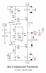
First turn Pot2 till you get a reading (voltage) over the bias resistor R10, then turn Pot1 till you get a similar (voltage) reading over the bias resistor R11.
In my opinion most important: keep your DC-offset at the output low (below 100mV) during biasing up. The target is to get this DC-offset as close as possible to 0 mV.
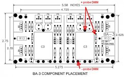
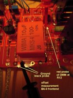
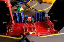
How to measure DC-offset shown in the following pics (I think you measured over the outputresistor - which is wrong - your red dots in your schematic).
Cheers
Dirk
you have a large DC-offset at the output of your BA-3.
No wonder, if I see the different bias -values of the N-channel and the P-channel.
First confirm, that your Pot3 is set to mid-position.
The biasing - procedure is described in the build guide.
First turn Pot2 till you get a reading (voltage) over the bias resistor R10, then turn Pot1 till you get a similar (voltage) reading over the bias resistor R11.
In my opinion most important: keep your DC-offset at the output low (below 100mV) during biasing up. The target is to get this DC-offset as close as possible to 0 mV.
How to measure DC-offset shown in the following pics (I think you measured over the outputresistor - which is wrong - your red dots in your schematic).
Cheers
Dirk
Attachments
Hello,
sorry that I am only now getting back in touch.
Thank you for your help.
I tried both tips, the result is the same.
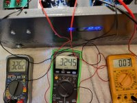
# ZEN-MOD, worked great with two measuring devices.
I only connected the 3. meter because of all values.
Maximum values measured above R10/R11.
P1 Maximum.
P1 = 326.2mV
P2= 324.5mV
DC Offset 0.03V
P3 = center
Can it be that Q1/Q2 has a low IDS?
sorry that I am only now getting back in touch.
Thank you for your help.
I tried both tips, the result is the same.
# ZEN-MOD, worked great with two measuring devices.
I only connected the 3. meter because of all values.
Maximum values measured above R10/R11.
P1 Maximum.
P1 = 326.2mV
P2= 324.5mV
DC Offset 0.03V
P3 = center
Can it be that Q1/Q2 has a low IDS?
Attachments
increase P1 and P2 to 1K
set to zero before starting again
confirm zero with ohmmeter, do not risk with CW and CCW fairytales
ref. to schm in post #1
set to zero before starting again
confirm zero with ohmmeter, do not risk with CW and CCW fairytales
ref. to schm in post #1

The voltage drop across R6 and R7 should read around 0,8V. This indicates that there is sufficient current running through the jfets to bias up the mosfets with a 500 Ohms pot.R6= 6,91
R7= 6,83
Hello,
I swapped the pots and was able to adjust everything.
Thank you once again for your help.
Dirk
I swapped the pots and was able to adjust everything.
Thank you once again for your help.
Dirk
Quick question when setting bias and dc offset for the BBA3. Can each board have one side of it done at a time with only 3 DMM or is it important to have 6 DMM with both sides of the board done together?
So does tying R5 together affect the opposite side when adjusting?
So does tying R5 together affect the opposite side when adjusting?
With the inputs shorted I've set each channel in single ended mode with 2 DMMs and then switched to balanced mode, because I was of the impression that tied together via R5 one channel did indeed affect the other. To make switching easy I have those small DIP-switch boards in the attachment installed. Credit for those boards goes to ItsAllinmyHead and the original designer whose name I sadly forgot. This being DIY I am sure he is happy with you having those Gerbers wherever he is.
Attachments
I set the bias and offset of the preamp last night. The bias and offset was not affected when adjusting one side of the channel vs the other. Haven’t been able to test yet but hope to tonight.
That dip switch is very cool, but in what scenario would it be useful? I understand the BA3 can take single ended sourced by tying pins 1 and 3 together with adapters.
That dip switch is very cool, but in what scenario would it be useful? I understand the BA3 can take single ended sourced by tying pins 1 and 3 together with adapters.
Oh yes. I forgot the thread is mostly for the BA3 amp.
I built the preamp to drive two F4’s as monoblocks.
I built the preamp to drive two F4’s as monoblocks.

I'm looking for help with the front end for a BA-3b with 32V rails. There's not enough room on the PCBs for the SILMIC 35V caps. What are my options to fix this?

You can squeeze them in and leave a bit longer leads on them. Have seen it quite often - looks only slightly ugly.
You could mount one on top and the other below bent horizontally or so.
You can buy fitting parts with more headroom regarding voltage rating too 1000uF50V.
I'd probably buy the fitting part, because I like a bit of headroom.
You could mount one on top and the other below bent horizontally or so.
You can buy fitting parts with more headroom regarding voltage rating too 1000uF50V.
I'd probably buy the fitting part, because I like a bit of headroom.
- Home
- Amplifiers
- Pass Labs
- Burning Amp BA-3b (Balanced)