perfect thanks...that makes a lot more sense now.think of them as adjustable Zener diodes
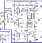
Here are those numbers with connection to input/R328 open (blue) and with 10k resistor to ground (black - highlighted):That you observed 115V leads me to suspect the meter somehow saw rail-to-rail supply voltage. Ground the black meter lead and measure each end of the resistor for insight.
So yeah I realised that by not "zeroing" the output side with the 10k resistor, the numbers might be rubbish. Sorry if I was confusing things there. And now the voltage drops are correct with both low-voltage ends being around +/-5V.
I also did some comparisons between Q318 (L) and Q418 (R). Once again I perhaps confused everything by not using the 10k grounding set up.
And of course, the voltage across C312 is 5V using the 10k ground! I guess I didn't fully understand what you were asking when you said to put the output stage into 0V output...now I think I see why the 10k resistor is critical to your troubleshooting. Sorry. I will now leave it 10k to ground unless stated otherwise!
That's a shift in the correction, but still suggests a problem in the input section.
So these stray volts could still be coming from the input feedback (L-FDBK) line? Not many more components on that side I haven't replaced already....
Thanks, that's fantastic progress! And more signs of health in the output stages.
So now let's focus on finding what's wrong in the input section.
I suggest returning to post #14 and reestablishing that last measurement: "-12V @ base of Q313/Q314 produces -11.6V @ TP2"
and your observation: " -12V though output section gave me -63.3V, which is +4 volts so I can see it is trying to do what you said!"
A large positive voltage should appear at R327, but isn't. So again confirm about -11V appearing at L-FDBK and that R327 voltage remains stuck in negative territory. Now to discover why it's not positive volts. Would you remeasure the all the same points you reported in your first schematic of the original post, in the left channel input section. Your original measurements may still be about the same. Most dramatically concerning is the -58V near the feedback resistors from L-FDBK. I imagine it will still be "interesting." I recall that you replaced Q309. Would you report voltages at Q303,304,309,310.
Thanks!
Edit: typo in list of transistors.
Last edited:
“Most dramatically concerning is the -58V near the feedback resistors from L-FDBK.”
Is that -58V actually -5.8V? Would be more reasonable but still not right.
Is that -58V actually -5.8V? Would be more reasonable but still not right.
Hi thanks for studying these ramblings further....I didn't manage quite so much time on it today however I now have updated voltages for the input section. These were done with the output section earthed via 10k resistor and R328 is not connected, as before.

The new measurements above don't really tell me anything, I hope they mean something to you! I have already replaced Q308, Q309, Q310, Q311, Q312.
I also don't really understand what the Q305/Q308 B-C shorts are meant to do.
I'm gonna stick my finger in the air....should Q304 be letting through more volts?
Yes, there's a tiny decimal in there, it is -5.8V.Is that -58V actually -5.8V?
and isn't. We definitely seem to have a large NEGATIVE voltage (-68.2V)A large positive voltage should appear at R327
I checked this and -12V into the output section gives -12.3V at R322/R319. Is that about right or very wrong?I suggest returning to post #14 and reestablishing that last measurement: "-12V @ base of Q313/Q314 produces -11.6V @ TP2"
The new measurements above don't really tell me anything, I hope they mean something to you! I have already replaced Q308, Q309, Q310, Q311, Q312.
I also don't really understand what the Q305/Q308 B-C shorts are meant to do.
I'm gonna stick my finger in the air....should Q304 be letting through more volts?
I suspect Q310 has failed. The evidence: Q309 collector is more positive than its base, suggesting it's saturated, and its's attempting to drive Q310. Base-emitter voltage at Q310 is apparently 1.1V, which is too large and should cause Q310 to be fully conducting--- but it isn't.
Remove Q310 and confirm failure. Then we have we'll have to find a substitute, as I believe the part is obsolete.
Remove Q310 and confirm failure. Then we have we'll have to find a substitute, as I believe the part is obsolete.
A Google translation of Wakh post above: "I think that Q304 pierced the base-emitter junction"
Thanks, Wakh!
My take is now wildly different from my earlier interpretation. I had overlooked 0.67V at Q304's emitter, I misconstrued Q310 base voltage as 66.2V, and also overlooked voltage at L-FDBK. Q304 is definitely defective, and voltages at Q309 base and emitter may be entirely normal with low bias currents. Plus the bias at L-FDBK is too small for a definitive experiment. 😕 😡 Maybe before coffee? Brain failure?😢
So let's start again. Was Q304 replaced earlier? Assuming base and emitter measurements are correct, it's definitely failed now. Maybe Q304 will be the only problem.
To test after Q304 repair, the output stage needs to be biased as before at -12V (or similar) so that L-FDBK is reliably negative with respect to the amp input stage. R327 should then show a large positive voltage. Then change output stage bias to +12V and then R327 should have a large negative voltage.
Once this is the behavior seen by the input section, you can think about restoring R328 to it's original position, no load initially.
Very sorry for leading you astray...

Ah yes, my European 7's perhaps look like a 2. So the B-E at Q310 is a healthy 0.6VBase-emitter voltage at Q310 is apparently 1.1V,
Oooh, I like this! Thanks Wakh. I don't quite know what pierced means in transistor-speak but I take it to mean not healthy!Думаю, что Q304 пробил стык база-эмиттер
Thanks Steve, your remote interpretation must be tough and not helped by my handwriting. Q304 has not been replaced yet. I have swapped Q310 a couple of times now and it made no difference (to what I was looking at anyway). I will put a SC1845 in as temporary replacement for the Q304 SC1775. Then I will do the +/- 12V feedback checks and will let you know.So let's start again.
There's no such thing as a negative result; it's all data! Thanks again both of you.Very sorry for leading you astray...
I have now replaced Q304. and I am getting +16.3V at the emitter....which I think seems better. The old Q304 passed superficial diode test out of circuit.
However, the amp failed the other tests:
-12V into output stage > -12V @ TP2 and -62.2V @ R327
+12V into output stage > +11.4V @ TP2 and -68.2V @ R327
Not much different to original testing figures a few days ago:
However, the amp failed the other tests:
-12V into output stage > -12V @ TP2 and -62.2V @ R327
+12V into output stage > +11.4V @ TP2 and -68.2V @ R327
Not much different to original testing figures a few days ago:
I guess I don't fully understand the feedback loop....what sort of figures should I get at TP2 with these +/-12V inputs? I can see that the highlighted lines above should give me positive volts at R327.+12V through output section gave me -67.7V
-12V though output section gave me -63.3V,
So we still have this problem I think. So there must be something else screwed as well....So again confirm about -11V appearing at L-FDBK and that R327 voltage remains stuck in negative territory. Now to discover why it's not positive volts.
Leave output biased at -12V since it provokes the failed state. Please report voltages at L-FDBK, Q303 emitter, Q301 all terminals , Q302 all terminal, Q304 all terminals, Q309 all terminals, Q310 all terminals, Q306 all terminals.
I hope these measurements will encompass the defective part.
Thanks!
I’m off to bed. TTYL
I hope these measurements will encompass the defective part.
Thanks!
I’m off to bed. TTYL
Last edited:
Ok here they are:Please report voltages at L-FDBK, Q303 emitter, Q301 all terminals , Q302 all terminal, Q304 all terminals, Q309 all terminals, Q310 all terminals, Q306 all terminals.
Q301/Q302 look happy in equal and opposites. I still don't understand the numbers at Q310. My suspicion is now Q303 and I might try replacing it as well today if I get a chance.
The problem feels like a transistor gone wrong....but could it be a simpler component?
Ok thanks again!
Voltage at base of Q310 looks suspicious. It should be about 1.2V lower than Q309 emitter (i.e. two diode drops, D303,D304) but is only about 0.5 or 0.6 lower. One possibility is open R324 or defective connections to the resistor. Probe directly across resistor body leads to confirm presence of ~66V. If supply voltage is there, resistor may be open. Another possibility is a shorted D303 or D304. Said differently, it appears that Q310 isn’t conducting enough base current to turn on. An open trace is yet another possibility.
Fingers crossed.
Fingers crossed.
Может эта картинка поможет?
Wakh, Спасибо, да, я думаю, что это другой взгляд на это, но вы понимаете эти схемы намного лучше меня!
Thanks, yes I think that is another way of looking at it but you understand these circuits much better than me!
So, I have news! You guys fixed it!
Already replaced it.Voltage at base of Q310 looks suspicious.
Already replaced these too!Another possibility is a shorted D303 or D304.
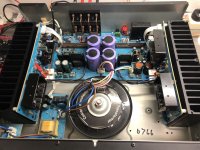
THIS WAS IT !!!! The amplifier now runs and music sounds clean through it....One possibility is open R324 or defective connections to the resistor.
I had measured R324 many weeks ago and it was high in circuit, but because it is located below a heat sink wall, I didn't really want to take it out so kind of forgot about it. So today with all your great advice, I realised I needed to dig it out and check it. I found it was open circuit, as predicted. Here is a photo of it's not-very-clever location (behind Q310 and the capacitor):
So I've still got to do the feedback check to help me understand the troubleshooting process. Also need to solder R328 back in and replace the rest of the heat shield then adjust the idles....I will do all that tomorrow. But I wanted to let you know it's fixed and that your help here was invaluable. I also would like to write up the conclusions here to end the post to help others in the future. But for now.....so happy it is finally working!!!!
Thank you thank you Спасибо
Attachments
For anyone who finds themselves here in the future - Summary of Faults and Parts Replaced
1) Protection mode, heat damage to Power Board, 68V power supply partially working and only producing +68V. No -68V.
Troubleshooting involved isolating the input from the output sections of the Power Amp Board, following the volts and testing the feedback response of the input circuit. At least I think that's what happened! I couldn't have fixed it without the knowledge and generosity of the people on this forum. 🙂
1) Protection mode, heat damage to Power Board, 68V power supply partially working and only producing +68V. No -68V.
- R721 (open and corroded from capacitor glue)
- R731 (burnt open, foil damage)
- R730 (burnt, foil damage)
- R735 (burnt, foil damage)
- Q710 (shorted SC1775 replaced with SC1845)
- Q711 (SC1775 replaced with SC1845)
- Q304 (SC1775 replaced with SC1845)
- R324 (open 100k Ohm 1/6W resistor under the heatsink wall)
- Excess heat on R334/R344 had cracked the solder and unglued the foil from the board
Troubleshooting involved isolating the input from the output sections of the Power Amp Board, following the volts and testing the feedback response of the input circuit. At least I think that's what happened! I couldn't have fixed it without the knowledge and generosity of the people on this forum. 🙂
- Home
- Amplifiers
- Solid State
- NAD C270 (C272) Power Amp Protection Mode - Stray Negative Voltages