

Post 1967:
Best,
Anand.
I also tried with another identical power supply but without the Saligny bridge and without the snubbers. I also tried with another stereo source. No changes.
Best,
Anand.
Hello,
I did some additional testing last night.
As a reminder: The amp as at the start with the Saligny analog power supply and everything else with a single input or none: no hum at all. Almost inaudible background noise in the tweeter.
I first reconnected the RCAs, then the protection modules and then tried the 3 power supplies.
I started with the SMPS Connex power supply.
RCA: ok, no hum
Protection module: average hum 1m but corrected. I had forgotten that with these modules, you need a 2x12v transformer and not a transformer with a single winding which supplies the two protection modules. I put a 2x12vAC transformer instead and the hum is gone.
Power supply:
Connex SMPS600RxE: a very light hum you hear if you stick your ears to the speakers.
Orange power supply with a classic bridge + 2 x 10KuF + 1uF MKP: The hum has increased and can be heard at 1m from the speakers.
Orange power supply with Saligny Universal bridge + 2 x 10KuF + 220nF MKP + 10K + led (original Tibi diagram): Powerful hum that can be heard several meters away. With the Saligny, we have 1Vdc more at the output.
I wanted to try with two power supplies but my second SMPS Connex is down (it sizzles but outputs 60v). I will try to tinker with a wiring with an analog power supply and the SMPS Connex. We'll see what gives but I think the hum will be zero.
What an adventure!
Stef.
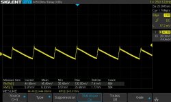
PS: I put you the measurements of the Saligny power supply loaded with a 2K5 power resistor. An excellent 44mVpp but some noise traces of MOSFET switching (we can't see them on the scope screenshot).
EDIT: the amp is currently running with the Connex on the Cantara. What a sound anyway!
EDIT2: I forgot. With the two analog power supplies, the Talema transformer becomes very noisy as soon as you turn on the amp (no sound if unloaded). I don't find this normal. DC from main?
I did some additional testing last night.
As a reminder: The amp as at the start with the Saligny analog power supply and everything else with a single input or none: no hum at all. Almost inaudible background noise in the tweeter.
I first reconnected the RCAs, then the protection modules and then tried the 3 power supplies.
I started with the SMPS Connex power supply.
RCA: ok, no hum
Protection module: average hum 1m but corrected. I had forgotten that with these modules, you need a 2x12v transformer and not a transformer with a single winding which supplies the two protection modules. I put a 2x12vAC transformer instead and the hum is gone.
Power supply:
Connex SMPS600RxE: a very light hum you hear if you stick your ears to the speakers.
Orange power supply with a classic bridge + 2 x 10KuF + 1uF MKP: The hum has increased and can be heard at 1m from the speakers.
Orange power supply with Saligny Universal bridge + 2 x 10KuF + 220nF MKP + 10K + led (original Tibi diagram): Powerful hum that can be heard several meters away. With the Saligny, we have 1Vdc more at the output.
I wanted to try with two power supplies but my second SMPS Connex is down (it sizzles but outputs 60v). I will try to tinker with a wiring with an analog power supply and the SMPS Connex. We'll see what gives but I think the hum will be zero.
What an adventure!
Stef.
PS: I put you the measurements of the Saligny power supply loaded with a 2K5 power resistor. An excellent 44mVpp but some noise traces of MOSFET switching (we can't see them on the scope screenshot).
EDIT: the amp is currently running with the Connex on the Cantara. What a sound anyway!
EDIT2: I forgot. With the two analog power supplies, the Talema transformer becomes very noisy as soon as you turn on the amp (no sound if unloaded). I don't find this normal. DC from main?
Attachments
Last edited:
Hello,
I tried with two power supplies. The Connex and the Saligny. No hum even glued to the tweeter. Same noise level as with the RCA input not connected. By ear, I hear no difference in background noise between the Connex and the Saligny. I will have to look at the levels with the scope.
Stef.
I tried with two power supplies. The Connex and the Saligny. No hum even glued to the tweeter. Same noise level as with the RCA input not connected. By ear, I hear no difference in background noise between the Connex and the Saligny. I will have to look at the levels with the scope.
Stef.
Last edited:
Hello Stef,
Why don't you try it with soldered contacts on the amplifier input. Your description suggests that there was current flow through the chinch ground of the source and that suggests that your pin connectors may be unsuitable.
Tim
Why don't you try it with soldered contacts on the amplifier input. Your description suggests that there was current flow through the chinch ground of the source and that suggests that your pin connectors may be unsuitable.
Tim
Hello Tim,
I will check that there is no bad contact but I checked with a multimeter when I made the JST cables.
I have the ad hoc PLIERS to crimp these tiny connectors. 😉
All FASTON connectors are crimped and then soldered. They are so tight that I have to use pliers to disconnect them.
If you have any other test ideas... because for now, I'm dry.
Stef.
Hello,
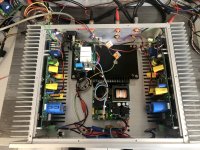
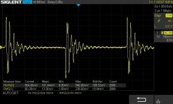
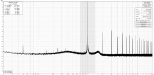
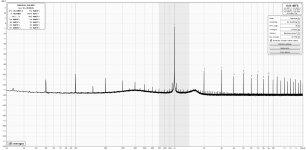
I boxed the amp with the Connex power supply. Everything is OK. No hum. I have given you the curve with the Saligny analog power supply in mono and the same but with the Connex power supply in stereo. The measurements are a little less good in stereo in the box with the SMPS Connex power supply, but that's relative given the levels.
Tonight I plug it into the Dynaudio Contour. 😉
I would look like that quietly with my prototypes the concern with analog power supplies which produce a more or less strong hum with a toroid which makes a very loud noise. I will resume my tests when I have a new generator and some components that I miss to do tests with analog power supplies.
Have a nice week end,
Stef.
Attachments
Hi Tim,
I'm about to start building your Q17 V13 SMD soon. I've got the PCBs (including the rectifier, softstart and speaker protection from your website) and all the parts now. But I've got some questions about the build, before I begin. Maybe you can answer them?
Also one last question: The chassis you are using in your pictures probably can't be used with the latest V13 boards, as they are 8,7cm wide, right?
I'll probably have to use a 120mm Dissipante, as nothing else is high enough.
Thanks
Lars
I'm about to start building your Q17 V13 SMD soon. I've got the PCBs (including the rectifier, softstart and speaker protection from your website) and all the parts now. But I've got some questions about the build, before I begin. Maybe you can answer them?
- On the underside of the Q17 PCB, there are two points labeled "wire". Do these need to connected by a wire link, or does it refer to the aircoil on the front? (If it is a wire connection, I'm curious, what's the reason of not having a trace on the PCB directly?)
- There are a lot of other markings for elements on the underside. Does anything else need to be attached from the there apart from the transistors? So far it seems to me, that they are all also marked on the upper side.
- What is adjusted by the pot and how an when do I do that?
- On both sides of the OPA1611 are pads marked "+" and "-". Do these have any significance?
- Right under the Q17 text on the PBC, there are three holes marked "+", "GND" and "-". Are these used for anything?
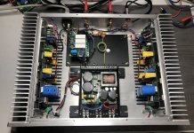
- Your rectifier board doesn't have any mounting holes. In your pictures it looks like you just have I lying in the chassis on it's side. Did you fasten it any way?
- How exactly do you run the grounds between all the boards? From your picture it looks like this to me:
- GND from the Q17 to corresponding Output GND on the rectifier
- GND from the rectifier's input from the transformers second winding to the speaker protection somewhere? Or the chassis? Can't see that properly. (Why only from one of the windings?)
- GND from the power plug to the softstart In PE
- GND from softstart out PE to the chassis?
- Also from softstart out PE to somewhere else, probably speaker protection?
Also one last question: The chassis you are using in your pictures probably can't be used with the latest V13 boards, as they are 8,7cm wide, right?
I'll probably have to use a 120mm Dissipante, as nothing else is high enough.
Thanks
Lars
Hello Lars,
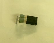
I advise you to put a small jumper for R32. That is to say solder a jumper of this style (see attached picture) and add the resistance of 10R above in addition. Just put the black jumper and the resistor is shorted. This will allow you to choose the config without suffering.
The Q17-Turbo is live but as I have people at home I haven't been able to do a comparison yet. It serves as background music. 😉
Thermally it is ok. It practically does not heat up and it consumes 30W in background music.
Regards,
Stef.
Attachments
Last edited:
Hi Lars,
The 2 connections labeled "wire" are a continuation of the tinned PCB area, which I also solder wire onto. In principle this can be omitted, however if you want maximum control of the speakers by the amplifier, thin traces are not an ideal conductor for high currents in a low impedance system.
It is a very handy aid in troubleshooting or modification to be able to see what is installed on the other side from below. Therefore I have extended the footprints with a backside labeling.
At the potentiometer (at Q14) first between (-) and gate of Q14 9k is set. If the LEDs start about the same time everything is ok. If the (-) side starts too late, or does not start (in this case switch off the amplifier) reduce the resistance at the potentiometer by 1k and start again.
The pads on the OPA have the meaning that you have measuring points for the voltage of the OPA, at the front of the board are also measuring points for the operating voltage of the driver stage. For the operation of the amplifier these points have no meaning.
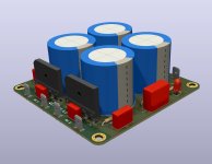
I usually get inflexible wires at the transformers, so I always have mechanical tension across the connecting wires, so I decided to make the board so that they are vertical in the case, with the screw terminals on top. Here the rectifier board rests on the cases of the electrolytic capacitors. If this is to be fixed, hot glue is ideal for this. I also use hot glue to fix the electrolytic capacitors and other components on the amplifier boards. This does not look nice, but it is a proven and reversible way to reduce mechanical stress on the components during loud music, as well as during transport.
The ground wiring looks like this for me:
1. cabinet ground, with protective earth of the mains connection and connected to the softstart at the PE point.
2. a completely separated input ground for the chinch inputs to the amplifier boards - no contact to the cabinet
3. a ground on the power side of the amplifier, this is built up in such a way that one cable each goes from the rectifier board to the amplifier and from the corresponding amplifier board one cable to the (-) pole terminal. The ground for the DC protection circuit can be tapped at the rectifier board as well as at one of the (-) pole terminals, since the internal resistance of the protection board is much too high for a relevant current to flow over it. This ground is also not connected to the protective earth or the housing. The reason lies in the fact that sometimes, source devices such as a sound card / CD player ... have a connection or resistance between input GND and protective earth. In this case, if the power ground is not disconnected from the housing, then there is a current through your audio cable and the older versions of the Q17 are deceased by oscillation.
Therefore, with this amplifier, it is important not to connect these individual grounds, but to wire them separately.
I also have narrow versions of the boards that fit into my chosen enclosures. The 87mm wide board is targeted for the Forums layout with 40 x 80 mm grid.
Regards Tim
The 2 connections labeled "wire" are a continuation of the tinned PCB area, which I also solder wire onto. In principle this can be omitted, however if you want maximum control of the speakers by the amplifier, thin traces are not an ideal conductor for high currents in a low impedance system.
It is a very handy aid in troubleshooting or modification to be able to see what is installed on the other side from below. Therefore I have extended the footprints with a backside labeling.
At the potentiometer (at Q14) first between (-) and gate of Q14 9k is set. If the LEDs start about the same time everything is ok. If the (-) side starts too late, or does not start (in this case switch off the amplifier) reduce the resistance at the potentiometer by 1k and start again.
The pads on the OPA have the meaning that you have measuring points for the voltage of the OPA, at the front of the board are also measuring points for the operating voltage of the driver stage. For the operation of the amplifier these points have no meaning.
I usually get inflexible wires at the transformers, so I always have mechanical tension across the connecting wires, so I decided to make the board so that they are vertical in the case, with the screw terminals on top. Here the rectifier board rests on the cases of the electrolytic capacitors. If this is to be fixed, hot glue is ideal for this. I also use hot glue to fix the electrolytic capacitors and other components on the amplifier boards. This does not look nice, but it is a proven and reversible way to reduce mechanical stress on the components during loud music, as well as during transport.
The ground wiring looks like this for me:
1. cabinet ground, with protective earth of the mains connection and connected to the softstart at the PE point.
2. a completely separated input ground for the chinch inputs to the amplifier boards - no contact to the cabinet
3. a ground on the power side of the amplifier, this is built up in such a way that one cable each goes from the rectifier board to the amplifier and from the corresponding amplifier board one cable to the (-) pole terminal. The ground for the DC protection circuit can be tapped at the rectifier board as well as at one of the (-) pole terminals, since the internal resistance of the protection board is much too high for a relevant current to flow over it. This ground is also not connected to the protective earth or the housing. The reason lies in the fact that sometimes, source devices such as a sound card / CD player ... have a connection or resistance between input GND and protective earth. In this case, if the power ground is not disconnected from the housing, then there is a current through your audio cable and the older versions of the Q17 are deceased by oscillation.
Therefore, with this amplifier, it is important not to connect these individual grounds, but to wire them separately.
I also have narrow versions of the boards that fit into my chosen enclosures. The 87mm wide board is targeted for the Forums layout with 40 x 80 mm grid.
Regards Tim
Hi Tim and Stef,
thanks for your replies. That answers all my questions.
I'll update here on the forum, once I get to actually do the build. Could be a while, but let's see.
thanks for your replies. That answers all my questions.
I'll update here on the forum, once I get to actually do the build. Could be a while, but let's see.
Hello,
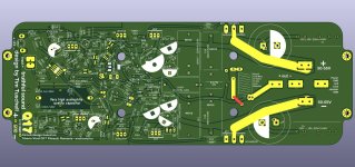
I provide you with a compact (102x102mm) and versatile power supply that I designed. There are several optional components but you can use it simply with only 2 bridges and 4 capacitors. I haven't tried it yet. To be printed in 2 Oz of course.
Files are available on my Github repository: Q17-PSU-1.0
Good evening.
Stef.
Attachments

Good evening,
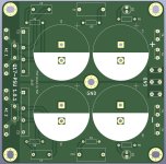
There is no space left on the PCB and some will want to put a bridge in place of the thermistor. 😡
Version 1.0.1 with an additional Faston connector on the GND.
Regards,
Stef.
There is no space left on the PCB and some will want to put a bridge in place of the thermistor. 😡
Version 1.0.1 with an additional Faston connector on the GND.
Regards,
Stef.
Attachments
Hello,
About my noisy toroid, I have a lead. I made a minimalist DC blocking circuit and the noise decreases greatly. Without the bridge, I hear the noise going up and down at times. With the brige, I hear almost nothing and there is no variation in the noise level. This must be added that the transformer is also under overvoltage. I have 243VAC at main power while the transformer is given for 230v.
I'm going to make a slightly more complete DC blocker and maybe complete the whole thing with MKP capacitors on the secondary of the transformer to see. I would also have to increase the load at the PS output but I have to find the right resistors in my stock. There, I put 2K5 3W.
Stef.
Attachments

- Home
- Amplifiers
- Solid State
- Q17 - an audiophile approach to perfect sound