Hello!
If you want clean analytic sound, this is not for you.
But if you want sweet JFET sound you should build this amplifier.
The JFET adds distortion. The level of distortion is set to THD 0.050%.
Mainly 2nd and 3rd harmonics.
This is fed into one high quality opamp that can drive headphones well.
The opamp can deliver like 100mA.
This schematic shows an amp for 32 Ohm headphones.
For other impedances I have designed additional schematics which will give the same sound quality.
I may post such schematics upon requests.
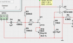

The gate of JFET is at 0.815Vdc.
The signal is 0.142 Vp at gate.
This is with an input of 0.358Vp to the C4 from function generator.
The R6 resistor is used to get less gain and let JFET do more gain. So increase dist.
The input is basically like Pass ZEN amp.
If you are familiar with ZEN.
I have added a 1k resistor to the opamp input.
The output impedance (although at 1MHz) is 26R, what does the frequency response come out as? (also it states 100pF load)
The 26 Ohms listed in the datasheet is open-loop. Even at 20 kHz Lineup’s circuit should have 60 dB of feedback so output impedance shouldn’t be an issue. I am curious how well that opamp handles 32-Ohm loads, though.
I do like the idea of this amp. I have been playing with a portable amp design that also uses a jfet input (but a discrete output); 20 j113s should be arriving in the mail tomorrow. I will probably breadboard this amp as well, only using opamps I have on hand like the njm4556.
Cheers!
Jason
I do like the idea of this amp. I have been playing with a portable amp design that also uses a jfet input (but a discrete output); 20 j113s should be arriving in the mail tomorrow. I will probably breadboard this amp as well, only using opamps I have on hand like the njm4556.
Cheers!
Jason
My simulation was not stable, so I have to add the 10pF capacitor.
Here is the frequency analysis:

Here is the frequency analysis:
Do you mean I should add a 100pF parallell with the 32 Ohm?The output impedance (although at 1MHz) is 26R, what does the frequency response come out as? (also it states 100pF load)
In that case the AC Analysis is the same. As the picture above.
Last edited:
Do you mean I should add a 100pF parallell with the 32 Ohm?
In that case the AC Analysis is the same. As the picture above.
The OPA1655 datasheet states the typical capacitive load is 100pF, 100mA short circuit current and the typical output impedance is 26R.
That sim has 4700uF on the output, 1uF at 20KHz will be about 2mA without a load, 4700uF by itself will be a large capacitance to drive, but 15/32 = 468mA (assuming a 15V rail to rail output). The load may be appearing like a short to the OPA1655.
I'm just a hobbyist so anyone please correct me if I'm wrong.
If you remove the 32ohm load is it still unstable?
I have added a resistor R12 in the output.
To ensure that amp is stable.
Now I have it stable with 1uF. And more.

To ensure that amp is stable.
Now I have it stable with 1uF. And more.
Last edited:
The OPA1655 datasheet states the typical capacitive load is 100pF, 100mA short circuit current and the typical output impedance is 26R.
That sim has 4700uF on the output, 1uF at 20KHz will be about 2mA without a load, 4700uF by itself will be a large capacitance to drive, but 15/32 = 468mA (assuming a 15V rail to rail output). The load may be appearing like a short to the OPA1655.
I'm just a hobbyist so anyone please correct me if I'm wrong.
If you remove the 32ohm load is it still unstable?
The datasheet has plots of open-loop output impedance as well as open-loop gain as a function of frequency. If I remember my circuit theory correctly, the closed-loop output impedance is smaller by a factor of (1+T) where T is the amount of feedback in the voltage domain. The proposed circuit has T of at least 1000, and the worst case open-loop output impedance is about 40 Ohms at 20 Hz. So the closed-loop output impedance of the opamp in a typical circuit would less than 40 miliOhms. Any additional output components you add would of course increase that.
I am not going to touch the stability question since i am not qualified to answer it. At some point you just need to build and test it.
Jason
Why not cap couple into the opamp and use a dual supply? You can eliminate the output cap and still get the distortion from the fet.
Or use the circuit as is, it is DIY.
Or use the circuit as is, it is DIY.
Well it certainly adds noise, around 40nV/√Hz. For a headphone amp that could be a problem...The R6 resistor is used to get less gain and let JFET do more gain. So increase dist.
With all those high value resitors around the JFET gate then the R7 1k is redundant BTW.
From a noise perspective you should do the gain first, then the attenuation, from a headroom perspective you should do the attenuation first, then the gain. If the headroom is adequate I'd suggest gain first is the way to go.
Here is new version.
With even more JFET Sound/Distortion 🙂
THD 0.080% at 10mW output into 32 Ohm.

With even more JFET Sound/Distortion 🙂
THD 0.080% at 10mW output into 32 Ohm.

Distortion is usually (almost always?) larger for larger signal levels. I would recommend simulating the signal levels that are typical for you with your particular 32-Ohm phones. I suspect 1.6V p-p is way more than you use, but I could be wrong.
For example, my 32-Ohm AKGs and Grados are about 100 dB/mW, so 1.6V p-p would be 110 dB. I typically listen at 70-75 dB, so 20 mV p-p would be my baseline, with dynamic peaks perhaps up to 200 mV p-p.
Would also be worthwhile to simulate the noise levels. I don’t use Tina, but in LTSpice the noise simulations let you see the contribution from each component.
jason
Last edited:
Neat project. I wouldn't get too hung up on the exact distortion figure. The simulation models are typically not great at predicting distortion.
Another approach to low-order harmonic distortion is provided by Nelson Pass's H2 Harmonic Generator. Maybe that could also provide some inspiration. He basically voltage-starves a common source JFET stage to get the distortion. You can dial the distortion to taste by tweaking a pot.
Another thing to play with could be to split R4 into two 20 kΩ resistors. One connects to the output of the opamp (as you currently have). The other is AC coupled to the output of the amp. That'll eliminate nearly all of the distortion of the output cap, assuming there is any.
Just suggestions. It'll be interesting to see how the circuit performs in the lab.
Tom
10mW (1.6Vpp into 32ohm) is +20dB. So it would be 120dB in Grado.Distortion is usually (almost always?) larger for larger signal levels. I would recommend simulating the signal levels that are typical for you with your particular 32-Ohm phones. I suspect 1.6V p-p is way more than you use, but I could be wrong.
For example, my 32-Ohm AKGs and Grados are about 100 dB/mW, so 1.6V p-p would be 110 dB. I typically listen at 70-75 dB, so 20 mV p-p would be my baseline, with dynamic peaks perhaps up to 200 mV p-p.
Would also be worthwhile to simulate the noise levels. I don’t use Tina, but in LTSpice the noise simulations let you see the contribution from each component.
jason
Yes, at lower levels the distortion would not be much. You are right.
At 1.6Vpp we need much more distortion.
I see what I will do.
Nelson Pass H2 generator is one way to go. As mentioned here.
He has already done this.
- Home
- Amplifiers
- Headphone Systems
- HP Amp with JFET Sound and Distortion THD 0.050%