hi guys.
I wanted to ask you a question.
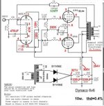
I want to make this amp,
https://diyaudioprojects.com/Schematics/DIY-Push-Pull-PP-6V6-Tube-Amplifier/
but I want to rectify with a solid state, and I have 2 JJ capacitors, one of 32-32uf 500v and another of 50-50uf also 500v, but I don't know what resistance values to put on them, has anyone already made a source like this? or I can repeat the values of the schematic for 6z34 that nothing happens.
As you will realize I lack technical knowledge to do mathematics
Thank you very much for the tip
I wanted to ask you a question.
I want to make this amp,
https://diyaudioprojects.com/Schematics/DIY-Push-Pull-PP-6V6-Tube-Amplifier/
but I want to rectify with a solid state, and I have 2 JJ capacitors, one of 32-32uf 500v and another of 50-50uf also 500v, but I don't know what resistance values to put on them, has anyone already made a source like this? or I can repeat the values of the schematic for 6z34 that nothing happens.
As you will realize I lack technical knowledge to do mathematics
Thank you very much for the tip

Sounds like a good job for PSUD2. https://www.duncanamps.com/psud2/
Check the 6V6 datasheet to see what a typical amount of current is and you should be able to simulate the power supply.
Check the 6V6 datasheet to see what a typical amount of current is and you should be able to simulate the power supply.
You could try it, but the first power supply dropping resistor will have to be a larger value,
to compensate for the tube rectifier's larger voltage drop.
Maybe 120 ohms to 150 ohms, whichever gives the right B+ value.
I would also use a 20W part for that first resistor.
Make sure the silicon diodes you plan to use are adequately rated in voltage.
The 1N4007 might just barely work, but I'd use two in series for each, they're cheap.
i was trying with a 100ohm 15watts drop resistor, to start.
astouffer, i dont use windows, thanx
I was reading this as to guide me
http://www.valvewizard.co.uk/smoothing.html
astouffer, i dont use windows, thanx
I was reading this as to guide me
http://www.valvewizard.co.uk/smoothing.html
Welcome!
The classic Dyna design is not very picky wrt to the supply voltage, so you can “play around”, as the schematic shows between 300V and 325V. If you can master the handy PSUD2 simulation program (not difficult) you could explore the options, otherwise we will try to help you.
In that case we need to know if you already have the Hammond 272HX power transformer, or are you able to entertain options.
I use PSUD2 on my MACastouffer, i dont use windows, thanx
I use linux, but I'm going to try to emulate it.
i have the hammond power transformer.
I'm going to try the software, but maybe something more classic is better, maybe someone has done something similar and can explain it
i have the hammond power transformer.
I'm going to try the software, but maybe something more classic is better, maybe someone has done something similar and can explain it
Very highly recommended to gain deeper understanding of designing power supplies for tube amps:
Designing Power Supplies for Valve Amplifiers
https://www.valvewizard.co.uk/Book4.html
Designing Power Supplies for Valve Amplifiers
https://www.valvewizard.co.uk/Book4.html
I am also a Linux user. LTSpice runs very nicely on Wine on Linux, and I've been using LTSpice for all my simulation work for years.I use linux, but I'm going to try to emulate it.
If you haven't used LTSpice before, there is a bit of a learning curve. But once you get familiar with it, LTSpice is far more capable than PSUD or Tone Stack Simulator or other one-trick simulation software. Those simplified programs have their purpose for non-techie users who feel uncomfortable learning to work with LTSpice, but IMO LTSpice is not hard to learn, and its an amazingly useful and capable piece of software.
Simon Bramble wrote some very nice LTSpice tutorials that I found very helpful: http://www.simonbramble.co.uk/lt_spice/ltspice_lt_spice.htm
For your purposes, you can put together inductors in LTSpice (and add mutual inductance) to turn them into a transformer, or you can take the much simpler route of clicking and placing voltage sources to represent your transformer voltages. Set them to 60 Hz AC at whatever voltage matches your use-case. Add series resistance to match your transformer (measure with a DMM).
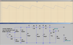
The attached image is a power supply simulation I did with LTSpice back in 2020 to help out another diyAudio user with questions similar to yours (he wanted to use a silicon bridge rectifier). This particular simulation shows the DC and ripple voltage right across the main filter cap fed by the bridge rectifier (C4). I've added a load (R7) to draw some current so that there is enough ripple voltage to see clearly in the simulation. 🙂
Hope that helps.
-Gnobuddy
Attachments
I also use linux (Fedora specifically)I use linux, but I'm going to try to emulate it.
i have the hammond power transformer.
PlayOnLinux does a fine job with running PSUD
https://www.playonlinux.com/
I am testing with LTSPICE, I am watching videos on YouTube to learn how to assemble the transformer, and the power supply, but I have one question, how much is the value of the load resistor? is the amp resistor value, right?
and I must know what is the value in henries of the secondary coils (300v)
and I must know what is the value in henries of the secondary coils (300v)
I was learning how to make the power supply, but I have some doubts, if someone who knows can see my schematic, it would be appreciated.
I don't know how much the voltage should be that goes to the 100k resistors, which go to the 12ax7 valve and the coupling capacitors
I don't know how much the voltage should be that goes to the 100k resistors, which go to the 12ax7 valve and the coupling capacitors
Attachments
Member
Joined 2009
Paid Member
I would like to offer a suggestion.
By all means learn about circuit simulation, but as you are not yet familiar with the tools and what is needed to do this then I would say do that later. Just begin to build the circuit, start the work. It takes time and effort to collect all the parts and build a tube amplifier and it’s good to get started!
It is also possible to get a few different value resistors and try them out, choose the one that gives you the preferred voltage. Start with the highest value resistor (lowest voltage). I like those low cost white rectangular 20W ceramic resistors and I used a couple recently doing something similar to drop voltage in a power supply.
Last edited:
thanks for the suggestion!!
By the way, what voltage should I have in the section that I indicate in the image? according to I read something like 200v.
to know how much the voltage drop should be from 300v

By the way, what voltage should I have in the section that I indicate in the image? according to I read something like 200v.
to know how much the voltage drop should be from 300v
Member
Joined 2009
Paid Member
I ran a PSUD simulation for you, using the winding resistances published by Hammond for the 272HX transformer.
http://www.hammondmfg.com/pdf/EDB272HX.pdf
I assumed nominal output but those Hammond transformers are designed for use with either 115V or 125V mains so results will depend on your mains voltage. At a current of 75mA (total) it seems that a resistor after the solid state diodes of roughly 420 to 470 Ohms does the trick. But best to have some different values on-hand.
Note that power dissipation in that resistor can not be simply calculated from the average amplifier current because the rectifiers will be flowing pulses of charging current hence 20W is still going to get pretty warm. Using two 20W rated resistors of twice the desired value each, placed in parallel, will give you the right overall resistance but now with 40W rating.
The 6SL7 has a high value anode resistor to achieve high voltage gain, don’t worry for now about the voltage on the anode as 200V is fine. Think of this, those front end triodes maybe drawing 1mA, which means a voltage drop of 100V across the 100k anode resistors.
Others have built this amplifier, you can find more published data. An example of voltages from a version built by another DIY’er is attached by my searching up here: https://boffin.nl/wp/6v6-push-pull/
Attachments
Last edited:
- Home
- Amplifiers
- Tubes / Valves
- 6V6 solid state power supply