I think Cal made some really big 36in x 36in ones with big drivers (Radio Shack branded Fostex possibly). I can’t remember which. But they were played outdoors at a DIY get together at Planet10’s place.
Great idea for wedding gift. They do depend on a wall to give them the bass. Out in the open I am not so sure how they sound.
I feel like the 28in size with a Faital 4FE32 might be a nice combo. 91dB and good highs and a powerful motor for horn loading.
Great idea for wedding gift. They do depend on a wall to give them the bass. Out in the open I am not so sure how they sound.
I feel like the 28in size with a Faital 4FE32 might be a nice combo. 91dB and good highs and a powerful motor for horn loading.
I think Cal made some really big 36in x 36in ones with big drivers (Radio Shack branded Fostex possibly). I can’t remember which. But they were played outdoors at a DIY get together at Planet10’s place.
Great idea for wedding gift. They do depend on a wall to give them the bass. Out in the open I am not so sure how they sound.
I feel like the 28in size with a Faital 4FE32 might be a nice combo. 91dB and good highs and a powerful motor for horn loading.
Thanks X! I was thinking the 28" might be nice as well. Maybe Cal will chime in as well.
Just wanted to post this for a laugh but also a proof of concept. I've been kicking the idea of a spiral horn loudspeaker around for a while now too and just now found this thread in a google search. But I had a couple of different ideas...
First, what if you made the horn itself the driver by either activating the innermost edge or perhaps a part of the spiral at the 1/2 or 1/4 wavelength. So I mocked up a proof of concept 🤣 with a small tube, an old hard drive connected to a headphone plug, some cardboard, paper, and tape. You can hear sound coming from the bare hard drive, but with the horn on there, the bass response is actually quite surprising when you put your ear next to it. I get full range with great bass! I can tell that it could be better though if the horn was better fixed and the rod better connected to the arm of the hard drive, but for a quick test, it ain't bad LOL.

More realistically though, instead of driving it from the center with the driver on the flat face, what if you put a ramp inside the spiral down to the tip such that the horn was the same rate of area increase as a typical voigt tube/BIB with the driver faced out from the 1/4 or 1/2 wave point in the horn installed in the outer curve? Basically, make a voigt tube with the driver on the triangle side, then set it on the floor long ways, and curl it up with a bigger horn exiting vertically, and the sides become a single curve wrapped up in itself. In this way, the horn portion could create an entire wall of sound. Maybe even tuck the driver inside the spiral (keeping it on the curved wall) such that it interacts with the horn in a sort of single driver push pull configuration and the driver itself doesn't interfere with the sound exiting the horn and you get power from both directions of cone movement with all of it coming out of the horn?
Thoughts? Anyone smarter than me know how that would (or wouldn't) work acoustically?
First, what if you made the horn itself the driver by either activating the innermost edge or perhaps a part of the spiral at the 1/2 or 1/4 wavelength. So I mocked up a proof of concept 🤣 with a small tube, an old hard drive connected to a headphone plug, some cardboard, paper, and tape. You can hear sound coming from the bare hard drive, but with the horn on there, the bass response is actually quite surprising when you put your ear next to it. I get full range with great bass! I can tell that it could be better though if the horn was better fixed and the rod better connected to the arm of the hard drive, but for a quick test, it ain't bad LOL.
More realistically though, instead of driving it from the center with the driver on the flat face, what if you put a ramp inside the spiral down to the tip such that the horn was the same rate of area increase as a typical voigt tube/BIB with the driver faced out from the 1/4 or 1/2 wave point in the horn installed in the outer curve? Basically, make a voigt tube with the driver on the triangle side, then set it on the floor long ways, and curl it up with a bigger horn exiting vertically, and the sides become a single curve wrapped up in itself. In this way, the horn portion could create an entire wall of sound. Maybe even tuck the driver inside the spiral (keeping it on the curved wall) such that it interacts with the horn in a sort of single driver push pull configuration and the driver itself doesn't interfere with the sound exiting the horn and you get power from both directions of cone movement with all of it coming out of the horn?
Thoughts? Anyone smarter than me know how that would (or wouldn't) work acoustically?
Last edited:
I’m sorry I am not understanding what you are doing. Using the voice coil of a HD head as the transducer? Where is the membrane?
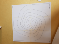
Maybe a sketch of what you are proposing with a coiled up BIB etc would be helpful. The horn expansion of the Cornu is non linear and has quite an expansion compared to most BLH’s. The area of the driver membrane comes out to a horn area equal to depth of Cornu x perimeter. For standard 28in x 5.5in that is 4x28in x 5.5in or 4312in^2 from a 12.6in^2 Sd of a 4in driver. That’s a 342 area expansion.
Maybe a sketch of what you are proposing with a coiled up BIB etc would be helpful. The horn expansion of the Cornu is non linear and has quite an expansion compared to most BLH’s. The area of the driver membrane comes out to a horn area equal to depth of Cornu x perimeter. For standard 28in x 5.5in that is 4x28in x 5.5in or 4312in^2 from a 12.6in^2 Sd of a 4in driver. That’s a 342 area expansion.
Just noticed this.
Yes, the 36" were the RS-1354 5.25" drivers. They were quite bassy even out in the open. I made the 48" for aa Airborne 6.5" wood cone driver.
I find the 27" a little too small, with that 'bass hump' a little too high. IIRC it was up around 150 Hz?
Yes, the 36" were the RS-1354 5.25" drivers. They were quite bassy even out in the open. I made the 48" for aa Airborne 6.5" wood cone driver.
I find the 27" a little too small, with that 'bass hump' a little too high. IIRC it was up around 150 Hz?
Attachments
Here's a quick and dirty drawing. In the hard drive mockup (not meant to demonstrate the drive, only the horn), I'm using the inside edge as the membrane which is probably not ideal, but I think an electrostatic membrane (or just a normal driver) installed on the curve at the 1/2 wave point like a BIB might be better, but there's 2 horns in one that way because the back radiation uses the same horn as the front but at different points. I was sorta hoping it would just naturally work as it's essentially pumping air with both sides. But perhaps a double horn would work better, or a resonant spiral space within the horn?I’m sorry I am not understanding what you are doing. Using the voice coil of a HD head as the transducer? Where is the membrane?
Maybe a sketch of what you are proposing with a coiled up BIB etc would be helpful. The horn expansion of the Cornu is non linear and has quite an expansion compared to most BLH’s. The area of the driver membrane comes out to a horn area equal to depth of Cornu x perimeter. For standard 28in x 5.5in that is 4x28in x 5.5in or 4312in^2 from a 12.6in^2 Sd of a 4in driver. That’s a 342 area expansion.
The signal path between the front and rear of the cone is quite small, so the cancellation pattern starts in an unfortunate frequency range.
Calculate it, you'll see.
Calculate it, you'll see.
That's exactly what I thought, but with such a complex structure, I wouldn't know how to begin to calculate it. I'll take your word for it, thanks.The signal path between the front and rear of the cone is quite small, so the cancellation pattern starts in an unfortunate frequency range.
Calculate it, you'll see.
What if you put a sealed tweeter at the very inside tip of the spiral and put a low range speaker at the 1/4 wave point on the outside? Something like this:
Sorry, I just noticed I'm probably hijacking a thread meant for a specific build. I just got a little too excited this morning. Plz excuse.
Last edited:
I think you have what is closer to a spiral BLH with a spiral wall mounted driver vs a flat side wall mounted driver. Interesting idea and can work but not a Cornu anymore.
weird oblique thinking so i kind of like it...if the structure is foamcore would a DML possibly help to either reinforce or cancel modal properties?
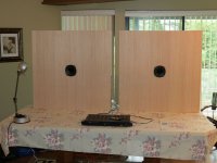
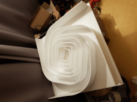
So I finally got around to trying to measure my “Modified Spiral/Large Cavity Cornucopyas”. These are modified from the standard design as detailed in posts #2798 and #2810 (basically much bigger cavity and longer horns).
Using REW V5.20.9 and a Umic-1 and trying to find my way into getting everything set up properly so these results may be completely wrong….
Set up uses laptop headphone output to feed a Cambridge A1 amp (volume 12:00, tone controls flat) then to the Cornu’s that are wedged/roof mounted in the “workshop/shed”.
REW is set up to select laptop speakers (Comcast Smart HD soundcard) with output volume set to 1.0.
Input Volume is set to 0.95.
Output level to -5dBFS.
Output sweep 30hz to 20khz.
Input length 1m 48khz sample rate.
Headroom is reported as ~7dBFS. (various gain settings were trying to get headroom close to ~10dBFS)
Umic-1 is taped to a tripod pointing at the centre of the speaker cone and ~55cm distance. There is a lot of stuff around speakers to confuse room response - its a busy and cramped workshop.
This is the resulting measurement.

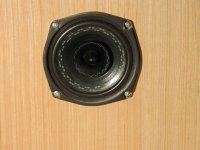
Remember this is a 3inch TC9FD18 in a plywood/foam-core box and stuffing was arrived at by trial and error to "sounds good enough". Not sure if most of the stuff below 100hz is proper sound or just the box resonating with the TC9 acting more as an exciter than a speaker – the front panel certainly shakes a lot at the low end.
The test signal was around usual listening level, lower volumes tended to leave the 30-500hz response similar but lower the 500hz plus curve by a few dB.
Although the response is ragged they actually sound quite good.
So – what have I got wrong in the set-up, what else should I be measuring, and any suggestions for improvements to set up or speakers?
Thanks
DonJ
Using REW V5.20.9 and a Umic-1 and trying to find my way into getting everything set up properly so these results may be completely wrong….
Set up uses laptop headphone output to feed a Cambridge A1 amp (volume 12:00, tone controls flat) then to the Cornu’s that are wedged/roof mounted in the “workshop/shed”.
REW is set up to select laptop speakers (Comcast Smart HD soundcard) with output volume set to 1.0.
Input Volume is set to 0.95.
Output level to -5dBFS.
Output sweep 30hz to 20khz.
Input length 1m 48khz sample rate.
Headroom is reported as ~7dBFS. (various gain settings were trying to get headroom close to ~10dBFS)
Umic-1 is taped to a tripod pointing at the centre of the speaker cone and ~55cm distance. There is a lot of stuff around speakers to confuse room response - its a busy and cramped workshop.
This is the resulting measurement.
Remember this is a 3inch TC9FD18 in a plywood/foam-core box and stuffing was arrived at by trial and error to "sounds good enough". Not sure if most of the stuff below 100hz is proper sound or just the box resonating with the TC9 acting more as an exciter than a speaker – the front panel certainly shakes a lot at the low end.
The test signal was around usual listening level, lower volumes tended to leave the 30-500hz response similar but lower the 500hz plus curve by a few dB.
Although the response is ragged they actually sound quite good.
So – what have I got wrong in the set-up, what else should I be measuring, and any suggestions for improvements to set up or speakers?
Thanks
DonJ
Attachments
That looks great. Your midbass might be a tad high and speaker could use a bit more stuffing until 200Hz is only 5dB higher than 10kHz. That might be more balanced for more genres.

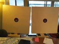
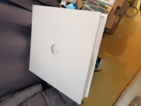
I've built this 56cm x 56cm cornu with FaitalPro 3FE25 a month ago.
It sounds good and comfort.
... more detail, more wide sound stage and obviously
more bass than my SoundArtist LS3/5A.
I can not come back to my LS3/5A.
Thany you for a great speaker.

It sounds good and comfort.
... more detail, more wide sound stage and obviously
more bass than my SoundArtist LS3/5A.
I can not come back to my LS3/5A.
Thany you for a great speaker.
Can I assume the 100hz dip is a half wave cancellation ?
The actual distance front to back ?
How long is the back horn/line ?
Or is that floor bounce cancellation ?
The actual distance front to back ?
How long is the back horn/line ?
Or is that floor bounce cancellation ?
@norman bates
Can I assume the 100hz dip is a half wave cancellation ?
<- I don't have any analyzing tool.
The actual distance front to back ?
<- 80mm guide-line height(depth)
How long is the back horn/line ?
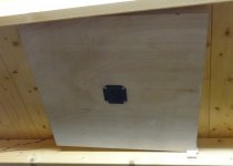
<- Check the attached image. I've scaled down the original cornu pdf document by Sebastian.
Or is that floor bounce cancellation ?
<- I don't know the meaning 'floor bounce cancellation', I'am sorry.
Can I assume the 100hz dip is a half wave cancellation ?
<- I don't have any analyzing tool.
The actual distance front to back ?
<- 80mm guide-line height(depth)
How long is the back horn/line ?
<- Check the attached image. I've scaled down the original cornu pdf document by Sebastian.
Or is that floor bounce cancellation ?
<- I don't know the meaning 'floor bounce cancellation', I'am sorry.
Attachments
-
 수정됨_cornu_01.png310.8 KB · Views: 215
 -
 수정됨_cornu_02.png333 KB · Views: 210
 -
 수정됨_cornu_03.png460.1 KB · Views: 191
 -
 수정됨_cornu_04.png396.4 KB · Views: 201
 -
 수정됨_cornu_05.png321.5 KB · Views: 205
 -
 수정됨_cornu_06.png313.6 KB · Views: 200
 -
 수정됨_cornu_08.png286.7 KB · Views: 218
 -
 수정됨_cornu_10.png398.4 KB · Views: 199
Nice construction details and great craftsmanship. Congrats on your new speakers. I like your front shallow horn.
Hi all!
Read all thread (fun weekend 😀) and I'm so excited to try Cornu Compact Horn.
Why not to try make version with no budget limit and see (or rather listen) what we can get
Can somebody with way more experience than me if it's possible or worth to make Cornu with these drivers:
Read all thread (fun weekend 😀) and I'm so excited to try Cornu Compact Horn.
Why not to try make version with no budget limit and see (or rather listen) what we can get
Can somebody with way more experience than me if it's possible or worth to make Cornu with these drivers:
- field coil EMS LB5EX ( http://www.emspeaker.com/fiche_LB5EX.pdf )
- Lowther DX65 ( https://www.lowtherloudspeakers.com/product/dx4)
Thanks in advance!
The DX4/5 appears to be closer to an 8in class driver. You would need to scale up the plans accordingly. The base plans are for a 4in driver in a 28in baffle. 8in driver would doubly be 56in wide square baffle. Massive.
The LB5EX is probably a 5in class driver and much more doable at 5/4x28in = 35in wide square baffle. Probably 4in to 5in depth is fine.
The Fostex FE103A can fit in the standard baseline plans just fine as it is correct 4in class driver.
Sound wise, the Fostex would be well suited. The LB5EX would probably work well too but I have no experience with them. The frequency response appears to have a step function in the mid range with a drop from 1kHz in up. But that might be a benefit - this speaker has gobs of bass and no baffle step compensation needed. It might need a front horn to help the highs keep up with the higher levels of bass output.
Why not to try make version with no budget limit and see (or rather listen) what we can get
That was the original inspiration, a big horn with a Lowther.
dave
There is IIRC, a full sized dual spiral bass horn that the person used as his floor. It was about 12” high. I’ll see if I can find it
- Home
- Loudspeakers
- Full Range
- Ever think of building a Cornu Spiral horn? Now you can!