PSUD2 is excellent for simulation purposes but what really matters is implementation, only then You can measure or hear how much ripple or other type of hum You really have.
I have built 4 tube phono stages, with & without regulators and the PSUD always gave excellent results for ripple but implementing it without hum or buzz is a different matter.
It does take a lot of practice ( & learning ) to build tube amp of any kind without hum ( on high efficiency horns of 96dB everythnig not right in psu, layout or wiring can be heard, for example ).
Personally I admire the guys who can build phono, line + se amp without noises on high eff. speakers, maybe only with natural tube hiss on levels we never listen at.
Best wishes at building, Krca
It's really great... we need to make a technical plan to know how much it can be heard. I tried many times for zero ripple at the output, but with the real circuit that will be affected by the fields.I tried many times for zero ripple at the output, but with the real circuit that will be affected by the fields.
Two filter stages are enough, and the regulator with MOSFET after that. dht tubes.. harder to remove hum.
I think you need to ballpark with PSUD2, then switch to LT Spice. The values you inputed into Spice don't make much sense to me. If your choke has 259 DCR, you don't need added resistance in the PSU. That's a lot of damping right there. It depends a bit on the transformer you settle with, but, for example, this gets you to 9 mV ripple:

If you really wanted to use a film cap for the final RC stage, you could with this. Curve is a bit round IMO but that's what you're asking for using a tube rectifier in a lot of cases.
Sketch it out in PSUD2 then move to Spice and I think you'll get better results.

If you really wanted to use a film cap for the final RC stage, you could with this. Curve is a bit round IMO but that's what you're asking for using a tube rectifier in a lot of cases.
Sketch it out in PSUD2 then move to Spice and I think you'll get better results.
Attachments

Thank you, again, @Thekak . After a bit more reading and simulating, I've settled on a paper design that I'll breadboard. Multistage seems to be the way to go, and I'll have about 200-300 uV of ripple.
Ale Moglia provided a nice PCB for experimentation:
https://www.bartola.co.uk/valves/for-sale/ht-supply-pcb/
I also stumbled across his 01a PSU. The tuning cap is a great way to raise the output voltage right to where it needs to be. This then becomes sort of a hybrid cap/inductor input design.

Ale Moglia provided a nice PCB for experimentation:
https://www.bartola.co.uk/valves/for-sale/ht-supply-pcb/
I also stumbled across his 01a PSU. The tuning cap is a great way to raise the output voltage right to where it needs to be. This then becomes sort of a hybrid cap/inductor input design.
Hi - just adding another example to this thread since I have the same question. I don't have PSUD or a scope so just measuring AC voltage with a multimeter.
In listening tests I prefer a smaller amount of capacitance like 50uF total in CLC or CLCRC using only DC Link polypropylene caps. Sounds more lively than with bigger electrolytics. 150mA supply at around 330V B+, SE 6B4G amp. So I'm walking a fine line between a lively sound and residual hum.
Could you advise on how much AC ripple you would find acceptable for no audible hum at the listening position?
PSU is GZ34 in hybrid bridge > 20uF > 5H > 30uF so CLC. Caps are DC Link. AC ripple is 10V on first cap and 250mV on the second cap.
So maybe add a further LC?
You want to aim for sub 30mV ripple on the opt to give sub 1mV noise. On the speaker terminals, assuming 30:1 ratio on the impedance between DHT and output.
I like tube regulators to supply SE amplifiers with a constant clean DC. I have multiple board designs for this.
I like tube regulators to supply SE amplifiers with a constant clean DC. I have multiple board designs for this.
I added a 1H choke and 1uF PIO cap and the ripple on the PIO cap went up from 250mV to 320mV...... thoroughly confused.....
I presume next step is to replace the 1uF cap with something like 12uF?

I presume next step is to replace the 1uF cap with something like 12uF?
In your listening tests thus far, has it been the value of the final capacitor that is having an effect on the sound, or is it a function of total capacitance in the PSU filter?Hi - just adding another example to this thread since I have the same question. I don't have PSUD or a scope so just measuring AC voltage with a multimeter.
In listening tests I prefer a smaller amount of capacitance like 50uF total in CLC or CLCRC using only DC Link polypropylene caps. Sounds more lively than with bigger electrolytics. 150mA supply at around 330V B+, SE 6B4G amp. So I'm walking a fine line between a lively sound and residual hum.
Could you advise on how much AC ripple you would find acceptable for no audible hum at the listening position?
PSU is GZ34 in hybrid bridge > 20uF > 5H > 30uF so CLC. Caps are DC Link. AC ripple is 10V on first cap and 250mV on the second cap.
So maybe add a further LC?
Last edited:
Good question - not sure, without PSUD (Mac user) I'm flying blind. Just experimenting. I know that my Russian KBG PIO caps sound the best of all the caps I've used but they're huge and I only have 1, 4, 6uf. Next best sounding are Kemet DC Link. It's a good idea to add a 0.47uF cap to one of the main caps.
You can use Google to figure out how to run PSUD on your Mac. It's not difficult.
Right now, your process of pulling the letters C-L-R out of a hat and arranging them with arbitrary capacitor values could use improvement!
I doubt that you would expect that adding a 1H choke followed by a 1nF capacitor would lessen ripple. So why would you expect a 1uF cap to? You're dealing with 150 mA here.
1. General case formulas for designing a choke input supply is:
60Hz power mains, full wave rectification (120Hz), critical inductance = 350/load in mA
350/40mA = 8.75 Henry. Use a 10 Henry choke.
50Hz power mains, full wave rectification (100Hz), critical inductance = 420/load in mA
So . . . 420/40mA = 10.5 Henry. Use a 12 or 15 Henry choke.
Caution: if you use a small capacitor in front of a "choke input filter" supply, do not resonate it at 2 x power mains frequency.
A high Q circuit there may increase the voltage beyond the circuit's capability, such as rectifier peak inverse voltage.
It might just bite when you turn the amplifier power Off at the Exact Crest of the power mains voltage. OUCH!
2. How much ripple for a single ended amplifier?
an example of ripple at the output of a single ended amplifier, to illustrate the concept, so you can calculate it yourself on your design:
2A3 output tube; 3000 Ohm to 8 Ohm output transformer.
2A3 plate impedance = 800 Ohms
Suppose the B+ ripple = 20mV
20 mV x 3000/(3000 + 800) = 20mV x 0.79 = 15.8mV ripple across the 3000 Ohm primary.
Root: 3000/8 = 19.4 turns ratio
15.8mV / 19.4 = 0.81mV (810 uV).
How about that!
How much ripple will you allow?
Depends on . . .
104dB/watt speaker
83dB/watt speaker
speaker in the living room
speaker 1.5 feet from your ear, right at your computer
Very sensitive headphones
Very in-sensitive headphones
I listen at 2 meters (6.6 feet), and at 2 feet too.
I pound my amplifier output hum down to be less than 100uV (< 0.1mV).
I stopped using DHTs years ago, I found it necessary to power the filaments with DC, not only to reduce hum, but more importantly to eliminate ripple sidebands on each and every musical note and each of its natural harmonics, as well as on test tones.
I only use indirectly heated tubes now, and AC filaments are just fine.
I do not use headphones.
Your needs may differ.
Happy designing, happy building, and then enjoy listening!
Last edited:
Good question - not sure, without PSUD (Mac user) I'm flying blind. Just experimenting. I know that my Russian KBG PIO caps sound the best of all the caps I've used but they're huge and I only have 1, 4, 6uf. Next best sounding are Kemet DC Link. It's a good idea to add a 0.47uF cap to one of the main caps.
I was wondering if the early stage caps had an effect in the sound or just the last stage. You don't need PSUD to experiment with that. It'd be nice to be able to use smaller physical caps of higher capacitance early in the filter and only use the big boys for good sound at the end. I like the ASC motor run caps but they're big too.
@6A3sUMMER great post. Thank you. But why did the need to use DC filament supplies make you quit DHTs ? With convenient solutions like @Rod Coleman 's regulators, it is minimal hassle other than heat sinking.
First of all for PS B+ problems it doesn't matter a Rat's Patooty whether the tube is DHT or IDHT.
What natters is the mu of the tube. The hum problem is much worse for low mu toobz with a low plate resistance (rp).
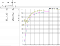
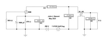
A voltage divider is formed by the tubes rp & the OPT. In the Sim that would be the 3K of the OPT & the 6W6 rp as a triode,
a bit less than One K in this case. The result is the One Volt PS ripple mostly appears across the OPT primary.😳
Bottom line, low mu toobz need a lot more PS filtering. 😀
What natters is the mu of the tube. The hum problem is much worse for low mu toobz with a low plate resistance (rp).
A voltage divider is formed by the tubes rp & the OPT. In the Sim that would be the 3K of the OPT & the 6W6 rp as a triode,
a bit less than One K in this case. The result is the One Volt PS ripple mostly appears across the OPT primary.😳
Bottom line, low mu toobz need a lot more PS filtering. 😀
Attachments
I seem to have generated a few questions and observations from others, so . . .
B+ ripple is one problem.
Just as discussed by jhstewart9.
DHT AC filaments is a different problem.
Hum is the least problem when using AC filaments.
Instead, intermodulation of 2x power mains frequency on all the signal frequencies is sometimes the bigger problem.
Upper and Lower sidebands anybody?
Believed by some, understood by even fewer, and successfully measured by the fewest.
Some DHT tubes are either un-obtain-um, obsolete-um, are not the decades old original designs, or are over-priced-um.
DC supplies for DHT filaments, whether brute force circuits, or Rod Coleman's regulators have more parts, more expense, and take up more real-estate and weight.
Also, the power transformer's filament winding's current rating should be 2 x the filament's DC current (to have a little margin), or go ahead and excessively Heat-Up the power transformer's filament winding!
That is most of the reasons why indirectly heated cathodes are now my personal choice.
YCMV (Your Choice May Vary).
Do your own designs!
If they are properly implemented, they will provide you with many hours of listening that sound good, are reliable, and safe.
Last edited:
This thread has been useful. I have three power supplies for various 2a3 SE amps. I've added a second choke to all three and they're all quieter. So CLCLC from now on. Chokes are getting expensive, unfortunately - Hammond prices have doubled this year in one fell swoop. Fortunately I still have some on the shelf.
I can only see only one good reason for using a choke in a tube power supply: filter out HF noise.
Using vacuum rectifier allows a gradual voltage increase to match other tubes. At one time this was the only choice.
However, maybe a better lower noise power supply can be constructed offering less size and heat? Vacuum rectifiers have several disadvantages, like size, heat, cost, durability, limited current capability resulting in narrow choice of filter capacity. Easier to get lower noise with a regulated MOSFET supply.
Transformers have resonant frequencies that will be excited by sharp rectifier diode turn-off times, which can be reduced with capacitor and resistor bypassing. Finding the resonant frequency with a tone generator and a scope is not hard. Band Stop filters can be constructed to reduce any relevant frequency content from this, if any. Most switching power supplies has serious line filters to get rid of conducted EMI.
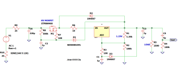
I included an example of a MOSFET/LM317 regulator for a preamp . LT1086 or LM317L is also usable here.
R8 + C2 gives a 7 second gradual startup. (I have a bunch of 7uF film-caps on hand, otherwise any suitable RC combination can be used.)
R6 can be used for a cheesy current limiting/protection with the value of the Zener diode.
The MOSFET burns off excess energy and needs to be heat sunk. The LM317 is set to drop out 3.5V (with the 10V zener) and limit the heat load of it here to 1/4W.
LM317 has low gain above 10KHz and bypass caps dominate noise performance above this, which hopefully should not be much needed.
Checking audio circuits with an scope is good to make sure some HF does not mess it up.
Using vacuum rectifier allows a gradual voltage increase to match other tubes. At one time this was the only choice.
However, maybe a better lower noise power supply can be constructed offering less size and heat? Vacuum rectifiers have several disadvantages, like size, heat, cost, durability, limited current capability resulting in narrow choice of filter capacity. Easier to get lower noise with a regulated MOSFET supply.
Transformers have resonant frequencies that will be excited by sharp rectifier diode turn-off times, which can be reduced with capacitor and resistor bypassing. Finding the resonant frequency with a tone generator and a scope is not hard. Band Stop filters can be constructed to reduce any relevant frequency content from this, if any. Most switching power supplies has serious line filters to get rid of conducted EMI.
I included an example of a MOSFET/LM317 regulator for a preamp . LT1086 or LM317L is also usable here.
R8 + C2 gives a 7 second gradual startup. (I have a bunch of 7uF film-caps on hand, otherwise any suitable RC combination can be used.)
R6 can be used for a cheesy current limiting/protection with the value of the Zener diode.
The MOSFET burns off excess energy and needs to be heat sunk. The LM317 is set to drop out 3.5V (with the 10V zener) and limit the heat load of it here to 1/4W.
LM317 has low gain above 10KHz and bypass caps dominate noise performance above this, which hopefully should not be much needed.
Checking audio circuits with an scope is good to make sure some HF does not mess it up.
Attachments
Uptic,
B+ power supplies
A preamp is one thing; a power amp is another.
CRC least efficient, too much loss in the R if you want low ripple, or just throw a few Farads of capacitance at it.
B+ voltage is at the mercy of the mains power voltage, and at the mercy of the amplifier Load current
C, Regulator, C not real efficient, the Regulator does have a burden voltage, and it needs additional voltage to be able to use a wide range of voltage from the power mains (or the regulation drops out). For all the tradeoffs, at least it IS regulated
L, C, R, C The R can make for low efficiency, but in most cases, there is more intrinsic regulation than the CRC filter.
B+ voltage is at the mercy of the Power Mains voltage.
For many amplifiers, this is good enough.
The above is just a very poor set of generalizations.
All designs have tradeoffs, or all the smart designers would only use one kind of power supply.
How about all the switcher supplies in my house that create all kinds of EMI interference?
The devices all Pass EMI Regulations, but they do not meet EMC (ElectroMagnetic Compatability)
Last edited:
Keep the minimum load current of the LM317 in mind.I can only see only one good reason for using a choke in a tube power supply: filter out HF noise.
Using vacuum rectifier allows a gradual voltage increase to match other tubes. At one time this was the only choice.
However, maybe a better lower noise power supply can be constructed offering less size and heat? Vacuum rectifiers have several disadvantages, like size, heat, cost, durability, limited current capability resulting in narrow choice of filter capacity. Easier to get lower noise with a regulated MOSFET supply.
Transformers have resonant frequencies that will be excited by sharp rectifier diode turn-off times, which can be reduced with capacitor and resistor bypassing. Finding the resonant frequency with a tone generator and a scope is not hard. Band Stop filters can be constructed to reduce any relevant frequency content from this, if any. Most switching power supplies has serious line filters to get rid of conducted EMI.
I included an example of a MOSFET/LM317 regulator for a preamp . LT1086 or LM317L is also usable here.
R8 + C2 gives a 7 second gradual startup. (I have a bunch of 7uF film-caps on hand, otherwise any suitable RC combination can be used.)
R6 can be used for a cheesy current limiting/protection with the value of the Zener diode.
The MOSFET burns off excess energy and needs to be heat sunk. The LM317 is set to drop out 3.5V (with the 10V zener) and limit the heat load of it here to 1/4W.
LM317 has low gain above 10KHz and bypass caps dominate noise performance above this, which hopefully should not be much needed.
Checking audio circuits with an scope is good to make sure some HF does not mess it up.
I would rather use a LM1117, also has a lower drop-out voltage.
It all seems rather excessive to be perfectly honest.
I also see very little benefits of having tubes in the power supply.
Except when you like the sound of the sagging of the voltage rail.
Which can be created with just a series resistor as well.
Andy if you give me schematics of each PSU I'm glad to help you simulating with PSUDII.This thread has been useful. I have three power supplies for various 2a3 SE amps. I've added a second choke to all three and they're all quieter. So CLCLC from now on. Chokes are getting expensive, unfortunately - Hammond prices have doubled this year in one fell swoop. Fortunately I still have some on the shelf.
- Home
- Amplifiers
- Tubes / Valves
- Advice on DHT B+ Ripple magnitude?