I still believe this DVM phenomenon is a culprit. Use the 3V range or higher for your offset measurements or use a filter in front of meter to suppress AC overload of meter.One thing that stood out is the OL readings at the TR13/14 and TR15/17 emitters.
I've investigated a bit further: when increasing volume, the multimeter in manual 300mV range shows a quickly rising voltage until it overloads. In the manual 3V range however, the multimeter shows a constant 0.007V. Wondering if there is an explanation for the different readings in 300mV and 3V ranges and if this could point to a potential fault.
Hi krais23,
I remain convinced that 7mVDC reading you observed using the 3V range on your meter is probably accurate and that the 300mV range can't be trusted because of AC overload. I can't imagine any other explanation for the change in meter behavior with change of range.
But some of your posts mention tripping of output relay into protection, so I can't reconcile that either. And rise in current is concerning as there's no output load connected, so increased current is unexpected/inexplicable--- right? Could you post some scope photos of output? If you DC couple scope, does scope confirm shifting DC with increasing amplitude? You might look for any DC between speaker ground and input jack or power supply common as drive is increased. HF oscillation remains a suspicion.
Thanks for indulging my curiosity. Good luck!
From my experience.
Using DMM in 300mV D.C range you can measure the D.C offset WHEN no signal aplied at the input.
Whatever you connect at the input,will overscal the DMM 300mV D.C range.
Using DMM in 300mV D.C range you can measure the D.C offset WHEN no signal aplied at the input.
Whatever you connect at the input,will overscal the DMM 300mV D.C range.
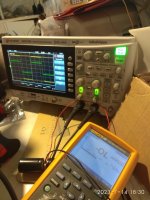
Have a look here.
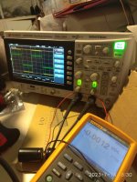
Both photos with same signal attached at the input but different D.C scals in DMM.
I the first photo DMM overloaded at mV scale.
In the second one at 50v scale offset is 1.2 mV.
Both photos with same signal attached at the input but different D.C scals in DMM.
I the first photo DMM overloaded at mV scale.
In the second one at 50v scale offset is 1.2 mV.
Attachments
Last edited:

The power supply ripple is probably within normal range.
The concerning thing is that the DC offet rises with volume which suggests that DC is passing through the volume control and input caps. Does the offset rise without any signal when you turn the volume up and down?
If it's affecting both channels, then maybe there's some kind of short or leakage between the two channels? Is there any dried glue on the PCB that could have become conductive?
Another thing worth doing is either taking the amp to another location without possible RF interference and see if that changes anything. Or put some severe input filtering in place to block any RF coming in and then re-measure.
Could also try increasing the frequency compensation to see if that changes things. Maybe these amps have too much bandwidth.
Just tested without any input signal: No rise in DC offset or bias current when turning up the volume.
Btw for all tests the speaker outputs are connected to an 8 ohm dummy load.
Btw for all tests the speaker outputs are connected to an 8 ohm dummy load.
I have already cleaned most of the PCB with isopropanol so that does not seem likely.If it's affecting both channels, then maybe there's some kind of short or leakage between the two channels? Is there any dried glue on the PCB that could have become conductive?
Just tested without any input signal: No rise in DC offset or bias current when turning up the volume.
Btw for all tests the speaker outputs are connected to an 8 ohm dummy load.
That's very encouraging.
So with dummy load, how do you know current draw is excessive? Not saying you're wrong--- just trying to understand the issues.
I haven't measured current but at ~10 o'clock volume setting the light bulb from the DBT already began to glow quite brightly. That and the fact that bias voltage had already increased from ~2.5 mV to 50-100mV and power rails were sagging lead me to believe that current draw must have been excessive.So with dummy load, how do you know current draw is excessive? Not saying you're wrong--- just trying to understand the issues.
So, try applying your test signal without dummy load attached. With luck, you'll be able to advance amplitude without seeing bulb limiter showing heavy current draw. Monitor output with scope so you can observe what's happening. At same time, monitor DC at output, but with a lowpass filter between output and meter: 100k in series and 0.1uF shunting meter to ground. Then you'll be able to trust DVM reading even with large sine wave applied.
I'm hopeful that that you've actually repaired all the defects. If so, you should be able to raise amplitude to near clipping and observe low offset voltage and modestly dim bulb. But again, this is without load applied.
If this is successful, then you remove DBT, keep offset DVM and scope attached, but connect 8 Ohm load. Raise test signal cautiously, looking for misbehavior. Appearances should be much the same with load now being driven.
Good luck!
Last edited:
So, try applying your test signal without dummy load attached. With luck, you'll be able to advance amplitude without seeing bulb limiter showing heavy current draw. Monitor output with scope so you can observe what's happening. At same time, monitor DC at output, but with a lowpass filter between output and meter: 100k in series and 0.1uF shunting meter to ground. Then you'll be able to trust DVM reading even with large sine wave applied.
I don't have a lot of time this week but just did a quick test without dummy load attached. Instead of using a lowpass filter I switched the multimeter in manual mV and V ranges to measure dc offset at the speaker outputs. You're on to something... in mV range setting the voltage was increasing rapidly to ~200mV but in V range the voltage reading stayed quite stable between 0.007-0.015V.
Yes, output relays have been tripping consistently. Not this time though.But some of your posts mention tripping of output relay into protection, so I can't reconcile that either.
One question I have though: even if the dc offset issue turns out to be a phantom phenomenon, wouldn't the sharply increasing bias voltage over both emitter resisters mean there is still a fault somehwere?
Yes, if you measure bias current developed across the pair of emitter resistors and it grows dramatically with amplitude, that seems problematic. If the bulb gets dramatically brighter, also not good.
I presume the oscillations remain unchanged?
I presume the oscillations remain unchanged?
Ignore that. I was confusing this thread with another that had oscillation mysteries.I presume the oscillations remain unchanged?
The 100MHz noise is still there. Even with the amp switched off but with input signal connected it's clearly visible in the preamp, power amp and power supply circuits. The input signal itself is clean.I presume the oscillations remain unchanged?
- Home
- Amplifiers
- Solid State
- Rega Mira 1: Rising DC offset in right channel