If you prefer active filters
And it makes sense with "Sub "crossovers at 80 or 60 Hz
Since passive coils would be large.
Far as plug and play.
2 wires and a amplifier make passive approach
Attractive as well.
2x 10" woofers are close to 90 dB
So never assumed high power.
Efficiency is very good for a average even large room.
Is rather fun idea.
Actual needed power is yes, not very high.
One of the reason I liked the idea.
Since is 2x subs and crossover is high at around 200 Hz
which makes passive design feasible.
It is my opinion that active drive of woofers, mid's & tweeters is far better without any passive components at all >Mids and tweeters: based on the speakers all having inductive voice coils, I would basically try a similar system as with the bass: put a passive inductor in series and make corrections with active filters. The learning curve may not be everyone's cup of tea, but I think combining analogue active + passive is better than just one or the other on it's own.
providing you have good amplifiers and preceding DSP based hardware capable of proper 'spectrum adjustment'.
Since we're way down a catacomb of weeds anyway, FWIW I agree, with the proviso that the "good amplifier" somehow provides a high output impedance. At least where it's most needed (at high frequencies where the speaker's own impedance climbs up to large values like 10-30 ohms vs a typical 3-7 ohm minimum impedance).
I'm starting to shy away from outright recommending current amplifiers, because of EQ quirks, they're hard to do, and the (relatively) low community support doesn't make it easier.
Pass' F2 rated at 80 ohms output resistance comes to mind as an exception. I haven't heard it but I imagine to get the best from it, woofer boxes would have to be oversized for low Q and maybe aperiodic to really flatten the bass impedance peak. Otherwise, you may end up distorting the bass twice: once by over-amplifying the resonance (with minimum feedback), and again with notch filters. And my limited experience with aperiodic boxes suggests that care has to be taken to avoid a dull overdamped tone.
So it's a bit of a mine field. Another idea would be to run low-powered speakers (mids, tweeters etc) with high power class-D amplifiers (which can be small and cheap anyway) and put a resistor in there, easily dividing the max voltage by some reasonable factor like 4 to 1.
Hot tip: if you're worried about thermal runaway due to the nature of current drive, just balance the power rating and temp-co of the resistors so that when the voice coil gets hot, it doesn't hog voltage because the resistors also get hot at a similar rate.
Last edited:
The theoretical perfect amplifier has the following characteristics:Since we're way down a catacomb of weeds anyway, FWIW I agree, with the proviso that the "good amplifier" somehow provides a high output impedance. At least where it's most needed (at high frequencies where the speaker's own impedance climbs up to large values like 10-30 ohms vs a typical 3-7 ohm minimum impedance).
1. Unlimited power.
2. Unlimited current capacity.
3. Zero output impedance.
4. Unlimited frequency bandwidth.
5. Zero distortion.
Such an amplifier does not care what speaker impedance or reactance it 'sees' and also provides ideal 'damping factor'.
* "Thermal runaway" applies to bipolar transistors that are over driven & under cooled. Mosfet transistors have a negative temperature coefficient.
Thermal runaway caused by 'overloading' a driver is something we just avoid.
Last edited:
I'd have thought that a non-varying output impedance of any magnitude would fit the description.3. Zero output impedance.
Why?A 'perfect' amplifier makes the "Current Drive vs Voltage Drive" > A PHURPHY.
First > Zero output impedance is a prerequisite for unlimited current capacity.
Second (above) > Because 'the perfect amp' can provide any amount of Voltage or Current as required.
Of course, if you want to rely on your amp to 'tune' your speakers > then that is a whole other 'imperfect' story.
Second (above) > Because 'the perfect amp' can provide any amount of Voltage or Current as required.
Of course, if you want to rely on your amp to 'tune' your speakers > then that is a whole other 'imperfect' story.
The current drive argument is not about imperfections of the amplifier, it's about correcting issues with the speaker.
Adding resistance to the output of an amplifier has the potential to produce an ideal result. What's imperfect about it?if you want to rely on your amp to 'tune' your speakers > then that is a whole other 'imperfect' story.
Not sure why you say this?Zero output impedance is a prerequisite for unlimited current capacity.
Re. zero output impedance & current capacity > It is simple electrical physics. (I thought you knew this)
Adding resistance to the output of an amplifier should actually be 're-phrased' as adding resistance to
the passive crossover/or section of - thereby achieving a desired result.
It should not be a function of the amplifier, but a function of crossover design.
Adding resistance to the output of an amplifier should actually be 're-phrased' as adding resistance to
the passive crossover/or section of - thereby achieving a desired result.
It should not be a function of the amplifier, but a function of crossover design.
The word 'limit', or limiter/limiting implies that it was relatively greater at lower levels and reduced in effectiveness as levels grew. However aren't we talking about a fixed resistance?
PS.
Adding resistance to the output of an amplifier essentially negates the use of low resistance/low loss speaker cable.
Adding resistance to the output of an amplifier essentially negates the use of low resistance/low loss speaker cable.
I was never talking about 'drive level non linearity' IE compression,The word 'limit', or limiter/limiting implies that it was relatively greater at lower levels and reduced in effectiveness as levels grew. However aren't we talking about a fixed resistance?
and yes, fixed resistance is of the DC domain > hence we call it impedance.
But let us not forget that 'proper' resistors have flat impedance.
Last edited:
A snippet from a Klippel article "Loudspeaker Nonlinearities – Causes, Parameters, Symptoms"

Running speakers 'wild' or with only active or DSP crossover over an amplifier with 0 ohm output impedance means that the varying inductance can create problems. The displacement from bass output modulates the gain at higher frequencies, so it's a source of IMD.
Adding an impedance in series makes the modulation a smaller fraction of the total.

A good bi/tri amping set-up requires an active crossover capable of proper spectrum adjustment.
A proper amplifier does not have problems with varying inductance. (except for Tube amps with Tx output)
There are actually erroneous problems with the above presentation.
A proper amplifier does not have problems with varying inductance. (except for Tube amps with Tx output)
There are actually erroneous problems with the above presentation.
Yep its not amplifier problem, but driver problem. BackEMF, voltage generated in driver motor makes relatively big current flow due to very low impedance in the circuit. Very low output impednce amplifier is effectively short circuit between driver terminals, which neans any voltage generated in the driver immediately turns into current, which makes force in the motor and the distortion is now in acoustic domain as well. Same with hysteresis for example, or microphonics, any current in the circuit turns into force in the motor and into acoustic domain.
Use cheap cable, a resistor, any series impedance with voice coil like inductor or high output impedance amplifier and this driver borne current reduces and acoustic distortion is reduced. Its not amplifier distortion but driver itself emitting its own.
One can be clever with it, low circuit impedance at driver resonant frequency where the back emf induced current actually works as advertized and makes electrical damping, but above this its distorion, no damping happening. Use series inductor for woofer, or parallel notch filter for cone breakup, and adjust frequency response with DSP. Best of both worlds, active and passive.
Well, of course distortion could be very low to begin with so perhaps not much audible difference.
The thing is that ideal amp with 0 output impedance cnnected to a transducer with moving coil with uber expensive short hifi cable makes all of the driver motor distortion mechanisms appear into acoustic distortion maximally, how crazy is that? 🙂
Last edited:
@tmuikku
Interesting & well written points.
It indicates that the 'ideal - zero impedance amp' can show & exacerbate problems with drivers.
I can now see how very specific use of passive components may aid a Bi/Tri active arrangement.
However, if I was involved in driver design, I would definitely use the closest thing to "The Ideal Amplifier".
https://simple.wikipedia.org/wiki/Lenz's_law
I would like to thank everyone for all of your contributions to this endeavor, even though some things have seem to have gotten out of hand. As I had stated in the beginning, I'm trying not to get too far off in the weeds with this. Although some have gone completely off the reservation.
I have been doing some homework and trying different methods. I have a preference to keeping all my drivers in a single line symetrically on the front baffle. I haven't decided on a particular configuration yet (TMMWW, MTMWW, or WMTMW). I'm sure there are many pros and cons to each as well as opinions to be expressed. The cabinet will be approximately 48 inches tall, approximately 14 inches wide and approximately 19 inches deep with a slot port at the bottom tuned to about 30Hz. The front side edges will have a 2" radius curve to help with baffle step loss. I will probably leave the front top edge a 90 degree corner. now, that y'all know know that, here are 2 crossover variants that have have evolved.
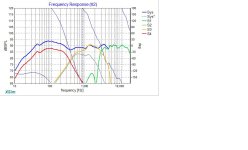
This first one is inspired by WhiteDragon's MTMWW configuration after I fiddled with it for a bit. And the corresponding Frequency Responses along with the Impedance chart
I have been doing some homework and trying different methods. I have a preference to keeping all my drivers in a single line symetrically on the front baffle. I haven't decided on a particular configuration yet (TMMWW, MTMWW, or WMTMW). I'm sure there are many pros and cons to each as well as opinions to be expressed. The cabinet will be approximately 48 inches tall, approximately 14 inches wide and approximately 19 inches deep with a slot port at the bottom tuned to about 30Hz. The front side edges will have a 2" radius curve to help with baffle step loss. I will probably leave the front top edge a 90 degree corner. now, that y'all know know that, here are 2 crossover variants that have have evolved.
This first one is inspired by WhiteDragon's MTMWW configuration after I fiddled with it for a bit. And the corresponding Frequency Responses along with the Impedance chart
Attachments
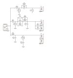
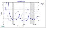
Then I came across a series style crossover diagram and worked with it for a bit and came up with this.


 Notice how the impedance level stays above 8 ohms. Is that a good thing? I also noticed that my efficiency dropped a little from this arrangement. But, the impedance level stays below 21 ohms. Good? Bad? Ugly? And I know someone is going to say something about all those resistors, I DON'T CARE!!! I understand there is some loss, But tell me why I see a mess of resistors in expensive crossovers. Also the reason for multiple resistors is to spread out the heat dissipation so as they don't burn up. Lastly, I'm wanting to use a Marantz Cinema 60 as my receiver/amp.
Anyway, thoughts? And thanks in advance
Anyway, thoughts? And thanks in advance
- Home
- Loudspeakers
- Multi-Way
- My first go at designing a cross over