A beta tracer should be capable of spanning four decades at least, and at different collector voltages, two decades in steps (1/2/5/10/20/50/100).The logarithmic horizontal axis (Icollector) spans 4 1/2 decades of current...
With acceptable accuracy, easy to operate, simple setting parameters and straightforward connection to a scope or xy-plotter.
I gave my H&H to my nephew, almost graduated in electronics, my clone.
Second thought: is to be preferred, even better!In your block diagram should`t the Vceset be below Rmeas?
There's no current loss with the mos and the INA doesn't care.
Initially I would not opt for that: I'm an old fashioned jfet-bjt-guy, and this would be easely done with a mosfet I'm not very used to work with. Though a voltage regulater with a power mos is the best solution I can master.
Btw, all input and comments, either pos or neg, are welcome. It's an untrotted path for me too!

Perhaps better to sense the base current directly with a second INA ? And remove the feedback loop ?Btw, all input and comments, either pos or neg, are welcome. It's an untrotted path for me too!
As far as I know, curve tracers always have a set of base resistors to choose from, so the sense resistor would be coupled with a INA gain selector.
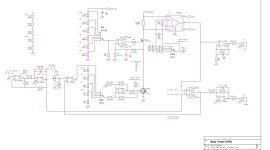
You could start to go more into detail with the schematic.
I'm interested to know how well your measured results compare with the datasheets? Are the datasheets usually accurate, or way off? Does it depend on manufacturer?It's 0745 here in the Pacific timezone. I just took my mug of morning coffee into the workshop and measured hFE versus Ic for a ZTX857 NPN transistor that was lying on the bench. Equipment is a LockyZ curve tracer plus the comes-with-Windows "Snipping Tool" to get a screen capture. I told the tracer to sweep Ic from zero to 30mA while holding Vce constant at 10 volts. So at the far right end of the plot, the instantaneous power dissipation during measurement is 300 milliwatts.
_
Ah! You put your feet in the trap!
No no no. Sensing the Ib is of no use (it's about the hFE = f (Ic) characteristic). That's my initial errand (edit: #2/#3). And by curious option (I've no better translation available), that very feedbackloop signal is the very beta curve, but due to the 'correction'-nature, inverted... only!
In my block diagram, this initial base curent is set by choosing 'in advance' the right Ic (aka Ib) setting to compare with the reference triangle source signal. The error voltage is the wanted fruit.
Last edited:
As far as odd 40 years matter, it's a mix of facts, promise and marketing. Thanks we're on scientific iceshelfs, so most can be considerd as reliable. But erosion happens more swift then expected in our time though.Are the datasheets usually accurate, or way off? Does it depend on manufacturer?
Edit: all from 20th century is solid. Then...?
I'm interested to know [whether] measured results compare with the datasheets? Are the datasheets usually accurate, or way off?
You'll have to perform that exercise yourself; I'm not volunteering. Maybe you could start by comparing the [published] hFE-versus-Ice measurements in Horowitz and Hill's book, against the [published] hFE versus Ice curves in manufacturer's datasheets. Remember that many BJT part-numbers are manufactured by more than one semiconductor company, so you will need to compare the H&H book's measured data against ALL datasheets from ALL manufacturers of a given part-number ... not just one datasheet.
When visualised on a scope or x-y plotter, an accuracy of 1% is normal.
Such a current converter is somewhat overdone.
I opt for generic components.
Such a current converter is somewhat overdone.
I opt for generic components.
Started with it, but a lot of component editing. And my job, of course...You could start to go more into detail with the schematic.
Great.
Because the common mode voltage needs to be within the rail voltages of the INA, Vce of the dut would be limited to <18V for most parts.
Best I have is INA103 with max. rating of 25V.
Personally I may not need more than 20 Vce...
It came to my mind while going through the datasheets of my stuff...

Because the common mode voltage needs to be within the rail voltages of the INA, Vce of the dut would be limited to <18V for most parts.
Best I have is INA103 with max. rating of 25V.
Personally I may not need more than 20 Vce...
It came to my mind while going through the datasheets of my stuff...
I took the INA128 because I use them at my work.
What would be the most suitable INA?
I'll have a look at the various available types (103 & 110 ?) - more suggestions for this application are welcome!
If Vce above 50V give to much hussle, I'll leave them out or indicate this in the design. Same applies to Ic currents above 100mA.
Both request a more robust design approach, something for an updated version later.
Tonight no progress: weeding the garden of my elderly (displaced to a caring house) neighbor (she's 90+), dense & overknee high growth...
If we use a asymmetric sawtooth generator, we can use the falling edge to trigger a monostable multivibrator with variable pulse width.something for an updated version later.
Something like CD4538.
From there a sample/hold freezes/updates the beta voltage for direct digital readout of hfe.
At the sampling point another very short pulse could be triggered, and a analog switch would add in a resistor parallel to the feedback resistor of the Y amp, so a small square bump cursor appears on the curve. Maybe you have another idea for a cursor.*
And while we`re at it, we could readout the current at the cursor position too. ☕
*We could couple a short hf burst into the Y signal, that would appear as a square dot 🙂
Last edited:
Refer to #12 to implement this feature.
The (only) readout unit I've in mind is an analog oscilloscope.
Those mentioned features (most) are already build in.
The (only) readout unit I've in mind is an analog oscilloscope.
Those mentioned features (most) are already build in.
Three ways to climb to the top.
Elaborous: start from the bottom upwards, reach an unexpected dead end, return, search for another route, progress further upwards till the next dead end, return... over and over. I call this the 'bug mode' (backwards Euler). There's infinite space, resources and time available, no worries. Fashionable these days.
Philosophical: consider the task, view at the map, plan the route, climb, rest, climb, rest... until the goal is reached. I call this 'god mode' (forwards Euler). Fortune telling, trickery, limitations. Tasks and fulfillment.
Natural: grow upwards without haste, each on its own pace, wanderings, lingering around. I call this the 'native mode' (moving avarage). Somehow, somewhere, sometime the end is reached. Scrabbling at the top.
I have a faint impression that my approach differs somewhat from the popular 'smart' rushings.
Back to the daily job.
Attachments
A beta tracer should be capable of spanning four decades at least, and at different collector voltages, two decades in steps (1/2/5/10/20/50/100).
I don't quite see how the hardware design in post #37 achieves a logarithmic sweep of collector current across the X axis (Ic from 1uA to 10mA) using a [linear] sawtooth as the stimulus.
Citizen produced a first design approach in no time and you complain about the linear scale ?
Did you hear about logarithmic amplifiers ?
In your screenshot from the ZTX the Ic scale is linear too.
Anyway, I would prefer the linear scale because I only want to know how a transistor performs in a predetermined limited Ic range.
Did you hear about logarithmic amplifiers ?
In your screenshot from the ZTX the Ic scale is linear too.
Anyway, I would prefer the linear scale because I only want to know how a transistor performs in a predetermined limited Ic range.
- Home
- Design & Build
- Equipment & Tools
- Transistor HFE - IC curve tracer?