In fact, I have already produced QUAD707. So there's no need to make QUAD606 again
However, due to some DIYER currently producing QUAD606 (TO3 transistor version)
I think this version is too difficult to install.
Moreover, QUAD707 has a relatively large width.
So I made QUAD606
In fact, he is almost indistinguishable from QUAD707.
Okay. It's just a difference in appearance. So I don't need to repeat the characteristics of this amplifier.
You can refer to QUAD707.
https://www.diyaudio.com/community/threads/quad-707-diy.399543/
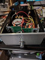
It's just that its shape is a bit different. It is more like the installation method of L20 amplifier.
I think it can replace QUAD405. It is indeed more effective than QUAD405.
There are many circuit introductions available online on QUAD606. Interested parties can simply go to Baidu.
However, due to some DIYER currently producing QUAD606 (TO3 transistor version)
I think this version is too difficult to install.
Moreover, QUAD707 has a relatively large width.
So I made QUAD606
In fact, he is almost indistinguishable from QUAD707.
Okay. It's just a difference in appearance. So I don't need to repeat the characteristics of this amplifier.
You can refer to QUAD707.
https://www.diyaudio.com/community/threads/quad-707-diy.399543/
It's just that its shape is a bit different. It is more like the installation method of L20 amplifier.
I think it can replace QUAD405. It is indeed more effective than QUAD405.
There are many circuit introductions available online on QUAD606. Interested parties can simply go to Baidu.
Attachments

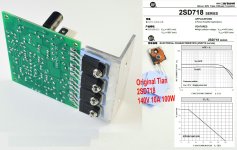


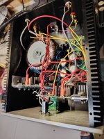
So there are three pairs of power devices, one pair at the upside and two pairs beneath the aluminium L bracket? Mind to share the schematics?
Best regards!
Best regards!
That's right. There are a total of 6 transistor outputs.So there are three pairs of power devices, one pair at the upside and two pairs beneath the aluminium L bracket? Mind to share the schematics?
Best regards!
I don't mind the circuit diagram. Because this was not designed by me.
You can search online. There are many genuine circuit diagrams for QUAD606
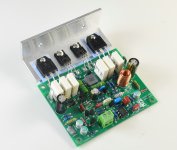
After I created the first version of QUAD 606. Found some minor issues.
Its signal-to-noise ratio is not particularly high. Then I improved.
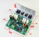
Now it's the second version. I omitted the first version of 20UH. Later discovered. This inductance cannot be omitted. So the second version added 20UH.
Then I assembled a self listening device. There is almost no noise. It's great.
Its signal-to-noise ratio is not particularly high. Then I improved.
Now it's the second version. I omitted the first version of 20UH. Later discovered. This inductance cannot be omitted. So the second version added 20UH.
Then I assembled a self listening device. There is almost no noise. It's great.