As we know, in 'the real world' many-many amplifiers sag @ 4 ohms > so they don't double in power compared to 8 ohms.
So, series wiring 2x 4 ohms stands to gain in relative output level. Double cone area also adds a 'synergy'.
A system efficiency of 82dB 1W/1M is just not realistic (without resistors) - It would be higher.
I now want to know what amp @ridnroundlost is using (?)
So, series wiring 2x 4 ohms stands to gain in relative output level. Double cone area also adds a 'synergy'.
A system efficiency of 82dB 1W/1M is just not realistic (without resistors) - It would be higher.
I now want to know what amp @ridnroundlost is using (?)
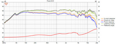
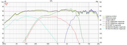
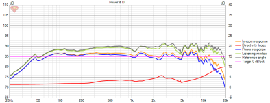
This chart shows the whole amplifier power going into each frequency as it goes. While this might be the correct way to generate the data, it is quite unrealistic. However it is wise to consider a worst case scenario nonetheless.each resistor in the mids would have seen over 80 watts
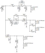
I guess at this point we should all remember that we've only seen ONE possible crossover design 'spat-out' from the Xsim program.Now for the brain blender. I have used the Xsim program to clank out a crossover for this Frankenstein. I am attaching pics of what I have brewed up thus far and for all to critique and tell me what I am doing wrong (aka suggestions, ideas, or I'm on the right path). Again, I'm not going for audiophile, this is a hobby not an addiction for me.
It seems general consensus that driving the woofers with resistors is a no go.
So, wouldn't it be interesting to actually see some alternatives presented by people!
I'd love to see some 🙂
Depends on the enclosure load & dimensions (including driver positions on the baffle & relative offsets), since without those and the attendent step-loss & diffraction, it's largely irrelevant as the filter designs will not carry over across different designs and they'd be of relatively limited use. Remember, even working up a complete, simulated design (especially with slightly dodgy levels for the woofers) means deciding on a box load, designing the cabinets, designing the baffles, splicing in the simulated loads & diffraction effects to the drivers, then doing an MP extraction on the FR & impedance before you can even get to designing the filters. With the best will in the world, that's not a ten minute process so will depend on how much free time everybody has. I'll try later so people can have a good laugh 😉 & no doubt others will too -but I've a shed-load of work to do first.
Last edited:
Right, probably makes sense.I guess at this point we should all remember that we've only seen ONE possible crossover design 'spat-out' from the Xsim program.
It seems general consensus that driving the woofers with resistors is a no go.
So, wouldn't it be interesting to actually see some alternatives presented by people!
I'd love to see some 🙂
Might have a go at it.
Curiosity is getting at me a bit
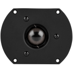
They have a truncated plate for that tweeter
be interesting to see how it goes D Appolito style
for mid +tweet
Last edited:
j\Just a quick look at my home work from the past few hours.
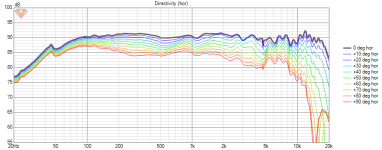
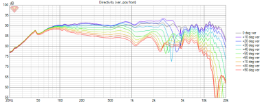
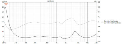
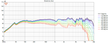
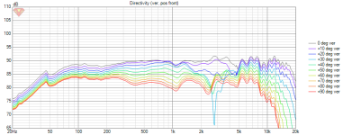
 I know someone is going to have an absolute come apart with the subwoofer circuit. But doing that brought down that region, just not quite enough though. Have a look see. It also has that funny hook between 40 and 50 Hz. I was looking around the internet and from my understanding, baffle step compensation is based on the width of the front baffle. And, the resistor and inductor are supposed to have set values. But, when I tried that, the frequency responce didn't look good. So, I fiddled with it for a bit till I got to this point. Also I did another Wattage disappation graph to see what kind of trouble that would be.


I had the source set to 100 watts for a worst case scenario. But, all this figuring on my laptop may be for naught. Scottmoose threw out a whole mess of things that looked like French to me.
It's late, I'm tired. Time for some rest.
Again, thank you all for this journey down this rabbit hole I am beginning. I sincerely appreciate the knowledge you all are giving. Thank you.
It's an artifact of how they took the measurements -in practice I doubt it's there as such.It also has that funny hook between 40 and 50 Hz.
Yes, for the first part, no for the second. Forget 'set values' -do what works. Most fixed figures are just keying off basic mathematical assumptions of a given set of dimensions; in practice, with real-world effects (diffraction kicking in, actual driver response) it usually isn't so pat as that alas -although that's also part of what makes it interesting / fun.I was looking around the internet and from my understanding, baffle step compensation is based on the width of the front baffle. And, the resistor and inductor are supposed to have set values.
Sorry about that. 😉Scottmoose threw out a whole mess of things that looked like French to me.
Short version is that somebody at Dayton has measured the bass units with a different method (drive level) to how the other units were done. 1m/w measurements are only comparable if all the drivers have the same coil impedance (Re), and preferably 8ohm. If they have different impedances, the output levels of the various drivers in practice will not be directly comparable. You need normalised 2.83v measurements (at a given distance, usually 1m) for that.
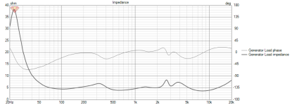
For whatever it's worth, you're crossing very low with those bass units, & even without an actual or a simulated box load, your low-pass filter is probably interacting with the driver's impedance rise at its Fs resonance (as in that ruddy great peak). Along with that ~170Hz crossover frequency is likely one reason you've got some titanic inductor sizes in there. In practice, I suspect you'll need to do a couple of things once you've got baffle-step simulated & spliced into both the FR and impedance responses: a slightly higher filter frequency, and probably a big LCR shunt across the driver to squash that low frequency impedance rise and ensure your filter works as intended. The values will still be large, but probably fewer in number. Conjecture as I'm writing on a laptop & not had chance to look at it properly -hopefully it could be avoided (no point in spending money if you don't have to) but I suspect something along those lines may end up useful, if you want to cross those woofers low. May. Possibly. Perhaps. Maybe. 😉
Think it only needs one mid
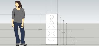
Did you sim the Baffle?
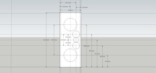
That is the spacing I used in the sketch up drawing.
Something I always do to make sure everything is good.
Unless you sim the baffle and center
to center spacing.
your shooting in the dark at how the
individual phase behaves. and where
actual baffle step is
I tried Appolito with drivers centered
and subs lower.
I could likely get rid of the series notch
if the mids were offset.
Was a idea, be easier with one mid.


Attachments
Last edited:
Back-calculating from the spec. sheet values, its listed SPL is indeed 1m/w, with 2.83v coming in at 91.8dB.
Scott, thanks for checking that. Testing at 1w/1m is annoying, posting conflicting information in the Spec Sheet PDF vs. the online product page is just sloppy.
@ridnroundlost - after baffle step losses you're around 86-88db system sensitivity. You won't need to pad the woofers with resistors. Also, you will only need a single midrange driver, and a single 8-ohm DC130B-8 will work.
Yet shifted it all to one mid for the cross. Points for creativity.Went full Appolito
Pleasure. Of course, we get to the next irony which is that the Omnimic FR data is allegedly normalised to 2.83v, although given the issues elsewhere I'm not sure I'd necessarily take that as read. 😉 it could be, as its average is lurking somewhere between the two, which isn't unusual so YMMV on that...Scott, thanks for checking that. Testing at 1w/1m is annoying, posting conflicting information in the Spec Sheet PDF vs. the online product page is just sloppy.
I've had a 'quick' (not so very) & rough (very) look at a TMMWW configuration 'just because', assuming the listening axis on the upper mid; 86dB was my average, more or less as expected. Nothing fancy, just went with the pioneer's offset B2 for a nice power response at the expense of the usual even-order phase alignment; fixed L-pads on HF & mids for impedance & level matching, oversized zobel & an LCR on the box impedance peak (kept it sealed). Lots of much more refined options possible, just a check to see roughly what could be done with my simple hat on while keeping the woofer low pass down at ~250Hz. All looks viable enough, though chalk up another who'd probably stick with a single mid.fter baffle step losses you're around 86-88db system sensitivity. You won't need to pad the woofers with resistors. Also, you will only need a single midrange driver, and a single 8-ohm DC130B-8 will work.
The twin would look good though. Pleasing symmetry. And lots of drivers.

Last edited:
Just TMWW would likely work well.
Keeps the tweeter up higher.
Never liked dual mids. Makes vertical difficult.
Easier with dual 3" mids but the sensitivity is way too low.
With 4" more possible. And different tweet
To keep center to center tighter.
Single 8 ohm version of the DC130
could make it work.
For good high power handling and crossing to a
5" I keep tweeters on 3rd order min.
Even though the Tweeter being used I believe
has Fs in 800 Hz zone.
Rear Chamber is larger, but doesnt mean the surround
is going to enjoy much below 2700 to 3200 Hz
then 3 rd order really help keep it clean at high power
Maybe look up prices on Bass coils.
One sim with 3x 16 mH coils
probably make you faint seeing the prices.
You should be able to hit 230 Hz to 190 Hz crossover
with around 6.8 to 8.2 mH
Last edited:
That looks like a far more feasible crossover design, and (at the right height) D Apolito is a very 'musical' arrangement for Mid & High,Went full Appolito
Way easier Both mids work well
View attachment 1191416
View attachment 1191418
View attachment 1191419
View attachment 1191422
View attachment 1191420
View attachment 1191421
View attachment 1191423
however I wouldn't go for Sub/bass drivers at top & bottom. Although it would quite determine size & shape of the enclosure,
I would place both Sub/low's at the bottom 'together'.
Yes Exactly agree.I wouldn't go for Sub/bass drivers at top & bottom
Keeps tweeter up higher. being a floor stander
actually still needs a stand for right sitting height.
Allen caught it. Instead of just removing a mid
I completely filtered out one mid.
One mid could work.
Its me im picky with vertical.
Any experiment ive done. MTM dont
seem to work unless very small mids.
for tighter spacing.
And lazy, got sick of working on it actually. LOL
truth be told
Yes > C8 @ 150mF did draw my attention, but I chose not to comment.
It is a rather unusual method of attenuation. I would use both mids @ equal drive (series) with a subtle Zobel R/C
and use simple two resistor attenuation.
Although it would be hand drawn, I am thinking about presenting a simplified C/O network using standard values.
It is a rather unusual method of attenuation. I would use both mids @ equal drive (series) with a subtle Zobel R/C
and use simple two resistor attenuation.
Although it would be hand drawn, I am thinking about presenting a simplified C/O network using standard values.
Ceiling treble that just cuts in at some frequency 1kHz or above is not pleasant.Its me im picky with vertical.
From what I have read here, the Dayton 10" subs wired as 2x 4 ohms have roughly the same sensitivity/output
as the Dayton tweeter (within a dB or two). However the Dayton mid/bass x2 are said to be of higher output.
So, with that I'm presenting a basic crossover network that has room for 'fun' tweaking.
There are two points I need to make regarding the design >
1. The resistors Rx & Ry are not only the means of mid/bass attenuation, but also a way to fine-tune response.
2. The reason I have not shown the polarity/phase of the tweeter is because I always determine this by ear,
by sitting in my listening position and using a 'phase flip/flop extension-lead switch' so as to make no mistake.
I am hoping that there are some 'smart cookies' out there to further elaborate on Rx & Ry.
*(if there is a way to import the values into simulation software, I would love to see the results)
Attachments
It is possible*(if there is a way to import the values into simulation software, I would love to see the results)
Assuming the idea would be to keep the listening position up high.
And going back too MTMWW format.
Most the issues with baffle step will be the mids
The visual aspect for most assume " centered" drivers which will increase
the baffle step.
Offset drivers would flatten the response, but might not like like the appearance.
Depends what the designer would want visual wise.
Keep in mind center to center spacing for a 5 1/4 mid will behave similar to a 10"
driver on the vertical. With MTM closer to 11"
Throwing some thoughts out there:
Subs:
Single coil + active low-pass filter. No capacitor shorting the woofers passively.
Baffle step for dual 10s? Just call it a bass boost.
I guess everyone is assuming that power levels will be sky-high based on car audio backstory. I run my single 10s at "family friendly" domesticated levels and the 2W rated 10 ohm series resistors never even got warm to the touch. I replaced them with 1mH inductors wound with 0.125mm wire and that doesn't get warm either! But it's logarithmic so you may find that it suddenly switches from cold to hot, depending on room size and what content is being played.
Consider this: a typical 60W soldering iron runs at approx 25% duty cycle (15W) to keep the tip at 300°C. The Dayton's 38mm voice may be slightly more robust than that, but not by much. How much could it weigh, maybe 10 grams? You'd need to find out what voltages you run your speakers at.
Mids and tweeters: based on the speakers all having inductive voice coils, I would basically try a similar system as with the bass: put a passive inductor in series and make corrections with active filters. The learning curve may not be everyone's cup of tea, but I think combining analogue active + passive is better than just one or the other on it's own.
- Home
- Loudspeakers
- Multi-Way
- My first go at designing a cross over

