When you simulate with choke input instead of cap input you will see that the voltage drops a LOT. You want 300V DC? with Choke input hope you got at least 400V AC coming off the transformer. See this quick example for the Hammond Power transformer I used above, and a Lundahl LL1673 15H choke (with soft start because I am using TV damper diodes).The PT-240 looks great but goes back to my original question of giving the rectifier (most likely a 5AR4) more AC voltage than the schematic calls for and then needing to reduce the B+...
Ian

Also, I imagine moving to a different rectifier like a 5U4GB with a higher voltage drop will bring down the B+ even more. I'll be feeding it off the 420V AC secondary which is a little on the high side but seems within reason.Want to reduce B+ voltage?
Move the input cap, 20uF to right After the choke.
Then, put a small cap before the choke (1uF, 2, 3, 4uf? as needed).
Take out that 500 Ohm resistor after the rectifier.
Then put in a 100 Ohm series resistor after the choke, and a 50uF cap after the 100 Ohm added resistor. That will get the ripple voltage back down to as good as, or better than it was in the original circuit.
And . . . your power transformer will run Cooler!
So to be clear as I had a hard time following... are you suggesting something like this? Trying to make sense of it but it's just my inexperience more than anything...
I hadn't considered a choke input as a voltage dropper in this case... I've heard of them but never used one (in the two amps I've built)... I'm new to PSUD but it seems super powerful. Any tips on load calculation?When you simulate with choke input instead of cap input you will see that the voltage drops a LOT. You want 300V DC? with Choke input hope you got at least 400V AC coming off the transformer. See this quick example for the Hammond Power transformer I used above, and a Lundahl LL1673 15H choke (with soft start because I am using TV damper diodes).
Thanks again!
Joneci,
Right.
Discounting the voltage drop in the rectifier (either solid state, or vacuum tube)
The absolute limit of a cap input filter is DCV could be as large as 1.4 x the ACVrms
The absolute limit of a choke input filter is DCV could be as large as up to 0.9 x the ACVrms
1.4/0.9 = up to 1.56 times more voltage out of cap input filter, versus choke input filter.
A 20uF cap input filter, versus a very low capacitance (1uF or other) modified choke input filter has a dramatic influence on DCV output.
If you use a low value cap as the input filter, make it a FILM cap. DC Link caps are nice here. Get one rated to 700VDC (or higher) so you don't need to worry. Why use film here? Because unlike electrolytic caps, they won't drift over time. 20 years from now a 1uF DC Link cap should still be 1uF. It could very well be that a 1uF input cap is enough... You can simulate the precise value you need.
Personally, I would ONLY use Choke input today (vs. cap input). Ok, maybe someone can come up with a maita supply instead of choke input supply that would float my boat, but that's a different story. 😉
With choke input, the choke also stores energy which it can easily release when needed. And it DOES do this. Your amp will sound much more dynamic and responsive and you will not regret it. BUT then you need to consider a different mains transformer, and will need to simulate your circuit as accurately as possible, etc...
For the simulation load, look at my example. I have 60mA for each 2a3 plus approx. 13mA for my input/driver tube (which is a triode strapped pentode). You will see that 50K ohms of resistance leading to ground in my simulation - 1k plus 49k ohm. This is because I have a couple of 100k Ohm 4-5 Watt bleeder resistors bypassing the caps to ground - to ensure the caps all are uncharged after the amp is turned off.
Yes, I try to account for stuff like that in my simulations. You will see that PSU-II won't allow some combinations, so you need to find small work-arounds. BUT it's results are highly accurate from my experience.
Ian
One more thing. If your mains transformer is good for 150mA then if you are using Cap input, you need to consider that it is only good for around 2/3 to 3/4 of that value. So around 100mA is what you can plan on getting out of it with a Cap input supply. Pushing that too much will be too hard on your mains transformer. It will get hot, and possibly vibrate too.
However with Choke input, you don't need to worry about that. If it can do 150mA then with Choke input it can pretty much do the full 150mA without risk of over-heating and vibrating, etc. That said, you need to check that your choke is OK for choke input... sometimes they vibrate if they are not really up to the task. This is the reason I always went for good quality chokes...
However with Choke input, you don't need to worry about that. If it can do 150mA then with Choke input it can pretty much do the full 150mA without risk of over-heating and vibrating, etc. That said, you need to check that your choke is OK for choke input... sometimes they vibrate if they are not really up to the task. This is the reason I always went for good quality chokes...
Last edited:
I think I'll proceed with the choke input... that said, I'm new to PSUD and even when matching your PS to get a feel for the program, I'm getting different values. Perhaps this is a different thread but is there a reason for this?For the simulation load, look at my example. I have 60mA for each 2a3 plus approx. 13mA for my input/driver tube (which is a triode strapped pentode). You will see that 50K ohms of resistance leading to ground in my simulation - 1k plus 49k ohm. This is because I have a couple of 100k Ohm 4-5 Watt bleeder resistors bypassing the caps to ground - to ensure the caps all are uncharged after the amp is turned off.
The way I imagine it is the V(I1) is the B+, correct?
I did start messing around with it today and it seems super powerful. Don't quite know all of the transformer specs as I don't have it physically in front of me so just guessed on that... but have something that looks reasonable for a 350V B+... any suggestions?
You can choose soft start if you are using TV damper diodes. They take at least 10 seconds to come up to power, so even this initial little spike won't really be there. The 2a3 tube heaters will warm up faster than the damper diodes.

If you have some RC circuit between the 2a3 and the input/driver tube, then you can imagine this second capacitor actually being in the circuit. Naturally the driver/input current draw is after the resistor, but PSU-II won't let you put it there.
The main thing is to get the total current draw and the transformer characteristics correct so you have a very good idea of what DC voltage you can expect from your circuit. Hope this helps. Email the transformer manufacturer and ask for DCR and off-load voltages.
Maybe it can do more things. Ideally speaking, the voltage you get at I1 will be your B+, yes. You can put in multiple current taps, but I have just always used ohm's law to calculate what voltages I would get after simulating my B+. Looks like you are using a newer version of the software. I will probably try it some day 😉
Ian
Last edited:
I am not familiar with the simulation software.
In case it does not have an entry for the DCR of the primary, you can compensate for that.
Here is an example of how to use the DCR of the primary (I made up a set of transformer specifications to illustrate the concept):
Made up transformer: 120V to 360-0-360V (3 to 1 step up).
Primary DCR 30 Ohms
Secondary DCR 80 Ohms, center tap, 80 Ohms
The 3:1 transformation ratio makes the Effective secondary DCRs be (30 Ohms x 3) + 80 Ohms = 90 Ohms + 80 Ohms,
which is a result of 170 Ohms, center tap, 170 Ohms.
This may help to get a more accurate result of the simulation compared to the actual results.
And unpredictable results. 😱A 20uF cap input filter, versus a very low capacitance (1uF or other) modified choke input filter has a dramatic influence on DCV output.
Not recommended, altho here on DIY it seems anything goes.🙄
jhstewart9,
Class A1 amplifiers, both Single Ended, and Push Pull . . .
With B+ input filters that are not exactly cap input, and that are not exactly choke input . . . can often, and do often, respond quite predictably.
But jhstewart9, you are also Correct.
One danger of an input cap of small uF, and medium inductance choke, is . . .
They resonate. Be sure the resonance is not at the rectifier alternation rate, 100Hz or 120Hz for full wave rectification.
Example:
0.5uF input cap, and followed by a 5 Henry choke is a series resonator at 100.7Hz. Typically the choke is followed by at least 10uF, so the total capacitance of that resonator is still very close to 0.5uF.
That resonance, is essentially at 2x a 50Hz power mains frequency, (100Hz full wave rectifier frequency).
Good luck with that combination!
It is Predictable . . . predictably Bad!
How about a different combination of capacitor and choke, and 60Hz power mains?
120Hz resonance anybody?
I do not use power supply simulation software.
But I do a first order calculation, using the low capacitance on the rectifier node, to predict the approximate B+ voltage out.
How many ways are there to "Skin a ___? No, do not get me wrong, I love animals.
All ideas require very careful analysis of the whole system.
That is how many ideas fail, one or more factors are not taken into account.
The original Tacoma Narrows bridge (de ja vu all over again). Hmm, did that bridge collapse due to an un-dampened resonance?
Last edited:
In my travels I met a couple of guys in Alberta that had done wind surfing at the Tacoma Narrows.Tacoma Narrows bridge
Just pulled up the forcast for tomorrow, looks OK. The bridge video was the real deal! 😀
It does. It has an off-load voltage calculator, and a source impedance calculator. You can also set the mains frequency and rectifier leak too.I am not familiar with the simulation software.
In case it does not have an entry for the DCR of the primary, you can compensate for that.

When used correctly, I find the results to be pretty accurate. Admittedly it took some investment to learn the SW, but that is always par for the course.
Ian
Last edited:
With all due respect to the 1940 Tacoma bridge disaster, 100kHz resonance (or 120kHz) can be cancelled if you want to do that. Loftin-White did that in 1930. They even used a 2uF input cap, 20Hy choke and then a 1uF filter cap.
see here: Radio News, January 1930
People somehow think the unique part of this design is direct-coupling. Imho it's the approach to noise cancellation that is most interesting.
Of course stability is what I would be MORE concerned about. Is the input cap 2.1uF or 1.85uF? You can easily see the BIG differences in B+ that ensue. And will the input cap value change over time? Best go for Choke input supply if you can do it, and if not that then use a decent value input filter cap on the supply.
Last edited:
@soulmerchant quickly on chokes… if I source a choke rated for the proper AC voltage, it should function in both a choke input and capacitor input correct? as long as the specs work with both application (henry, max current, etc.)…
looking at the bottom one specifically. though if it comes down to money i might have to go with a cap input unfortunately

looking at the bottom one specifically. though if it comes down to money i might have to go with a cap input unfortunately
@joneci - I sourced different chokes over the years. Some work as choke input and some don't. When they don't you know it because they will vibrate with choke input before they fail or whatever. All should work with cap input. I never actually had a choke fail...
For me, the choke can easily be fitted below my top plate. I have enough stuff on top of my amp already. Lots of space below. No need for fancy potted chokes on my amps. My current favorite choke is the Lundahl LL1673 / 15 H. No vibrations and only 60 Ohm DCR with each winding in series. Not sure what price you pay in the USA for them though.
Maybe you have a local supplier that makes nice DC chokes that can be used for choke input. Or maybe you can find a hobbyist on this board who winds chokes once in a while.... 😉
soulmerchant,
I think you meant 100Hz and 120Hz.
Not 100kHz Not 120kHz. Right?
My thoughts about 2uF, 20H choke, 1uF . . .
There will be Lots of Ripple, which then has to be cancelled in the amplifier topology.
Instead, get rid of almost all the ripple first, and then let the amplifier topology cancel the small residual ripple.
Back then, they did not have any inexpensive 500V large capacitance filter caps.
Today, we do not have an excuse for using 2uF, 20H, 1uF, . . . except to have fun repeating history.
Just my opinions.
The Lundahl looks great... will inquire with their sales rep here in the US.For me, the choke can easily be fitted below my top plate. I have enough stuff on top of my amp already. Lots of space below. No need for fancy potted chokes on my amps. My current favorite choke is the Lundahl LL1673 / 15 H. No vibrations and only 60 Ohm DCR with each winding in series. Not sure what price you pay in the USA for them though.
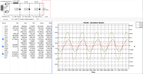
I spent the holiday working through PSUD and it's a great tool. I've been messing around and this is where I'm at... I've got the B+ around 350V and seem to have the DC ripple pretty smooth. I wonder... is there something I should be aiming for in terms of ripple? I've attached some images below... Any thoughts or feedback would be great.
Again it's for the following schematic... where I'd like to implement a choke input.
Attachments

That Rankin schematic is almost a pure choke input filter.
0.68uF input capacitor is just to adjust the B+ voltage slightly as needed.
No need to re-invent the wheel.
I notice you go from 100uF to 47uF to 10uF to get to the load.
You really need the most capacitance where the load is, so the power supply does not vary much as the output stage current changes.
Especially important for Class AB push pull, less important for Class A single ended.
I noticed that little cap... it's definitely an exercise to learn to design a choke input filter while seeing if I can use a slightly different transformer in this design. I've been considering a few schematics. This was closest to pure choke input so figured I'd start here; the other two are cap inputs.That Rankin schematic is almost a pure choke input filter.
0.68uF input capacitor is just to adjust the B+ voltage slightly as needed.
No need to re-invent the wheel.
I notice you go from 100uF to 47uF to 10uF to get to the load.
You really need the most capacitance where the load is, so the power supply does not vary much as the output stage current changes.
Especially important for Class AB push pull, less important for Class A single ended.
Working with PSUD I struggled to get the filtering right considering the current ripple with any other combination of values. Is there an approach or resource you might recommend?
This is something I put together this morning over coffee. Granted I went with a 5AR4 for less voltage drop but it seems to work with your suggestion. The RMS voltage sits around 350V DC as per the schematic. Thoughts? Thanks again.
Last edited:
joneci,
I have never run PSUD or other power supply software.
Software and I do not get along.
I do my own calculations by hand (lf course an understanding of the concepts is necessary before calculating).
It is all part experience, part iteration, and part having studied power supplies for decades (repair, design, schematic reading, failure analysis, etc.)
Just more than I would care to put into a thread here.
If I had time, I would do a power supply mini-seminar for our local audio clubs (two clubs and a common meeting).
But, instead I need to spend that time to prepare a mini-seminar on amplifier circuit tradeoffs: performance; simplicity/complexity; reliability; cost; and on and on.
Years ago I ran a mini presentation + lab listening session related to 300B parallel single ended versus 300B push pull, for VSAC 2008 (regrettably the last VSAC).
My first self study of electronics was the ARRL Radio Amateurs Handbook, 1956.
I tinkered with vacuum tubes, solid state, and worked most of my life in various electronics jobs.
US Navy and other US electronics schools, Oregon State for Engineering Physics and Math, and I opted out before I graduated (but put those classes to good work).
Happy designing, building, and listening.
- Home
- Amplifiers
- Tubes / Valves
- Effects of low voltage to rectifier tube