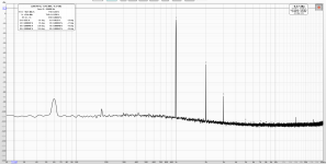
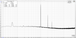
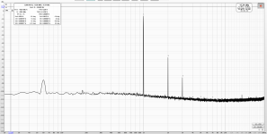
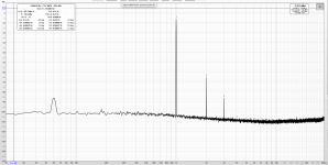
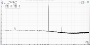
I tried a million permutations for a simple circuit about a year ago. I've been listening to the preamp I built with them since then. It's about as simple of a "tube" circuit as you can get. It has bypassed "cathode" bias and runs through a Tamura transformer (20k:600). Naturally the transformer is adding distortion, so take these with a grain of salt. But here are measurements that I made from 40V to 80V. All using a 442R resistor to set bias. I think the current was around the 5mA range or so? It's been a while. Regardless, distortion went down as voltage went up. At about 70V the gains got smaller, and it maxed out around 80V. This held true at any output level. Not sure what voltage these were taken at, but it was normalized.
BTW, my preamp is certainly not designed for high voltage swing. That's actually why I switched to a transformer from the preliminary choke load. It was just too much gain for what I needed. But the choke had better distortion numbers and more voltage swing. At any rate, I wanted a little "sauce" in there and what I landed on sounds great to me!
On that, I think I settled on 60V for the B+ and that ended up being 6 or 7ma.
Attachments


The settings for measurements were 0.1 NPLC which is 1.667 milliseconds per measurement. Average power is low during the measurement. The curves complete fairly quickly. Datasheet states 750 mW which I read as continuous. Momentary over max does not alarm me. The parts are pricey for sure. I am glad to have obtained some. I am planning to run the part at 45 to 50 volts Vds at 10mA. I burned in the part at 50v at 10 mA for some hours. I plan to attach a heatsink to the 2SK79.You took it up to 1.8 Watt!!!??? That's way over the specified limit. I would not do that with unobtanium parts.
Nevertheless your curves just confirm my earlier curve measurements. These parts are more linear at higher voltage and current.
I forgot to mention that I had a whole matrix of measurements. Different bias points and voltage settings. I noticed more correlation to lower distortion with a higher rail voltage (to a point) than with the current through the device. Current varied from around 3-4ma on the low end up to 8-9ma on the high. 6 or 7ma & 60V was just my "sweet spot" for sound as well as reasonable distortion numbers (mostly negative 2nd order).
THAT sounds a lot better for the bias point!I am planning to run the part at 45 to 50 volts Vds at 10mA.
If the power supply is 95 to 100v, the 2SK79 will swing into 2 watt territory. I am planning to use a tiny heat sink to dissipate some heat.
With a 100 V PSU and a 50 V / 10 mA bias point, you'd drop 50 V off the PSU at the load resistor, which would work out to 50 V / 10 mA = 5 kΩ. This 5 kΩ load line is shown in the attachment. Pretty decent, if you ask me. The dissipation on the 2SK79 would always be well below the 0.75 W.
How did you end up at the 2 W number?
How did you end up at the 2 W number?
Attachments
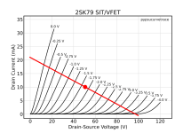
Good point. I was looking at the peak power of the family of curves.
When the 2SK79 is loaded with a buffer output stage, is the current through the 2SK79 increased?
When the 2SK79 is loaded with a buffer output stage, is the current through the 2SK79 increased?
A typical buffer will not draw any substantial amount of current. What type of buffer do you have in mind?When the 2SK79 is loaded with a buffer output stage, is the current through the 2SK79 increased?
I am going to lash up a version of Ben Mah's 2SK79 preamp. I will be skipping the input buffer. I think that the input buffer is not necessary. I will start with 100v rail voltage and 50v at T.P. I have some DN2540 devices on order. Target Ids for the 2SK79 is 10mA. I have burned in a 2SK79 at 50v at 10mA. The device seems happy. Very slight negative tempco at this bias.

Looks good. The DN2450 CCS will make for a nice flat load line for the 2SK79, unlike my drawing in post #27.
That output buffer will not draw any meaningful amounts of current from the 2SK79 gain stage.
I agree that the input buffer may not be necessary.
That output buffer will not draw any meaningful amounts of current from the 2SK79 gain stage.
I agree that the input buffer may not be necessary.
I received the DN2540 parts. I ordered some of the TO220 version and some of the TO92 version.
The temp coefficient is positive and the coefficient is rather large and pronounced. The 2SK79 temp coefficient is small and negative.
It takes a long time for the DN2540 current to settle. Once settled, a small change in room temp causes a large change in drain current. Using a 2SK79 as a current source in the gain stage seems a better idea than using a DN2540 there.
Does anyone have a suggestion for a current source that has a small tempco, low-ish noise, can swing zero to 100v and costs less than USD $50?
Gate leakage for the 2SK79 that I am experimenting with is <20nA at Vds=50V and Id = 10mA. DC input impedance is > 50 Megohms
I have TO92 DN2540 for CCS. I just checked the CCS for the 2SK79 in one of my channels and it seemed to be quite stable. I have it set for 3.5mA. Moments after power-up the current was 3.46mA. After several minutes it stabilized at 3.50mA. That was with the top cover off. With the cover on, the current was still 3.50mA. I took the cover off and used a piece of paper and fanned the air vigorously above the circuit. The current dropped to 3.46mA. So the current change was not large. The current re-stabilized at 3.50mA after a few minutes.
I am running the 2SK79 at Vds=70V for dissipation of 245mW. The 2SK79 specification for maximum dissipation at 25 degrees C is 750mW. I am at one third of the 25 degrees C maximum dissipation and I think that is a reasonable maximum taking the actual operating temperature into consideration.
I am running the 2SK79 at Vds=70V for dissipation of 245mW. The 2SK79 specification for maximum dissipation at 25 degrees C is 750mW. I am at one third of the 25 degrees C maximum dissipation and I think that is a reasonable maximum taking the actual operating temperature into consideration.
Ok. I will try to lash up an in-circuit version. Up to now I was biasing the DN2540 with a variable voltage source.
I lashed up a self-bias at 50v Vds. The source resistor will be between 220 and 240 ohms. I will make the source resistance 240 ohms and a 20k pot across the 240 ohms. That will allow me to dial in 10mA.
I used the DN2540 for CCS work a few times, and I never had any issues with drift due to temperature changes. Just give it a try and see how it goes.
- Home
- Amplifiers
- Pass Labs
- 2SK79 curves, musings