Recently, I purchased a diy kit of high power class A tube amp based on 805 (shugang FU-5). However, there is no assembly instruction except that they can only provide the schematic diagram and some photos of the finished product. Although I have some previous assembly experience of a low power tube amp based on 6L6GC before, I don't have experience for a tube amp that operates at as high as 1120V. So I have some questions on the circuit design of this amp especially for its HV power supply and its filtering. Also on how the appropriate testing procedure should be.
1. Regarding the HV power supply (1120V), 3 HV caps(180uF 450V) in series. Just wonder if the withstand voltage 450V is sufficiently safe for the shared operating voltage 370V? Supposed I'll add a resistor in parallel with the cap to ensure the voltage is equally shared. Or would it be better to add one more cap (i.e. 4 caps in series) so that the shared voltage will be less. Hence better margin?
2. About the LC filtering. 3 caps in series so that the combined cap will become only 180u/3=60uF. Just wonder if the hum noise is too large? Should I use larger cap value (say 1000uF instead of 180uF)?
3. There is a 100 Ohm VR at the cathode of FU5(805). Just don't know its function? How are we going to tune this?
4. For the filament supply for the FU5(805), there is a 0.1 Ohm in series to provide 10V filament voltage. Is it for the power up delay?
5. As the FU5(805) is directly heated and DC coupled from 6L6, any precaution on the testing procedures?
Need advice from someone who has experience on this kind of HV tube amp. Thanks.
Attachments
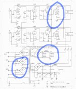
1. Yes definitely add parallel resistors. There was a recent thread here for calculating. I'd probably just go with 220k or 330k.
2. The filtering shouldn't be too bad. You can always simulate the circuit with psud2.
3. That is a hum balance pot. Adjust it for minimal hum at the speaker.
4. That is an RC filter.
5. The two pots on the bottom right control the 6L6 bias and ultimately the 805 current as a result. You would want to start with the maximum negative voltage at pots C1 and C2. That keeps the current at minimum and allows you to slowly raise it to the right levels.
For an amp like this I would definitely invest in a variac to allow for slow bringup and testing.
Good advice. Might be a good idea if you post the schematic here.
Build and test only one channel at a time. The DC supply voltage will be a little higher if you do this, but will be ok.
A Variac rated at 5 Amperes should be enough for the stereo amplifier, though you could get a higher rated one.
Make sure the Variac output is properly fused, since it can easily be damaged.
Hi astouffer,
Thanks for your advice.
1. Can you point out where the thread is for the parallel R calculation. Is the absolute R value critical?
2. You mean 180uFx3 is already good enough, right?
3. You mean the adjustment is by subjective hearing the hum at the speaker? Is it noticeable?
4. I heard that we may need to delay the turn-on of the 805 at power up in order to extend its life. Is it correct?
My understanding is that 805 is a direct-heated tube, so it is ON faster than the previous stage (6L6 which is indirect-heated). Hence we may want to delay the 805 filament heat-up until 6L6 is heated up to provide steady bias to the 805. Is it true?
5. Good advice. Will do this.
6. Will try to find one variac. By using a variac, do you mean that starting with a lower AC voltage (say 50-100V), check if all the DC supply voltages are correct (in proportion) before applying AC 220V directly.
Hi astouffer,
Thanks for your advice.
1. Can you point out where the thread is for the parallel R calculation. Is the absolute R value critical?
2. You mean 180uFx3 is already good enough, right?
3. You mean the adjustment is by subjective hearing the hum at the speaker? Is it noticeable?
4. I heard that we may need to delay the turn-on of the 805 at power up in order to extend its life. Is it correct?
My understanding is that 805 is a direct-heated tube, so it is ON faster than the previous stage (6L6 which is indirect-heated). Hence we may want to delay the 805 filament heat-up until 6L6 is heated up to provide steady bias to the 805. Is it true?
5. Good advice. Will do this.
6. Will try to find one variac. By using a variac, do you mean that starting with a lower AC voltage (say 50-100V), check if all the DC supply voltages are correct (in proportion) before applying AC 220V directly.
1. Here is the thread about balance resistors on capacitors. https://www.diyaudio.com/community/threads/calculating-balancing-resistors.393768/
2. The CLC filter should probably be enough. If not you could always add more filtering.
3. Yeah you can listen for minimal hum or go as far as an oscilloscope to measure.
4. This circuit is class A2 so the 805 should be drawing minimal current without any bias from the 6L6. A2 means the 805 grid will have lots of current flowing through. But to really get further in you'd have to figure out the operating points for this circuit and look at the 805 datasheet. I don't think a delay should be required but maybe someone with more knowledge than me can weigh in.
6. Exactly.
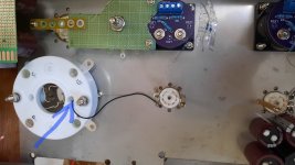
Regarding the 805 socket supplied, I find that its metal bracket is not grounded (i.e. floating). Just wonder if it is safe to leave it floating, as the nearby connectors are at HV. So I added a ground wire to connect it to the grounded metal cabinet. Is it the right way to do this?
Attachments
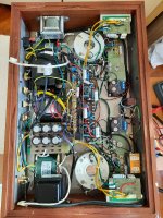
After a few months, finally I got the diy 805 amp assembled as shown. Just started to do the testing with the DC bias. Seems that the bias currents are OK for the 3 stages (i.e. ECC83, 12AU7 and EL34B). Next I plugged in the 805 tube without connecting the speaker. I tried to adjust the grid voltage and bias current. Then I observed that the grid voltage changed from -300V something and then rise up to near 10V (after EL34B was heated up). Nevertheless, at that moment I heard some noise (ro, ro, ro ....) from the OPT. In about a minute or 2, the fuse was blown up.
Just don't know what happened. Seemed the the OPT was burned. Measured that its primary winding is shorted to the secondary winding.
Someone said the I should test it with the dummy speaker load connected. But I'm not sure because later I really connected a dummy load. Unfortunately, the noise is still there.
Any idea from the expert?
Next I got the info from the DIY kit supplier that the dielectric strength of the OPT is 1200V. Supposed to be not high enough, because the B+ is already near 1100V. ??
Attachments
Yes, the dummy load is needed for testing. without it, the tube sees a high impedance, and the voltage-swing can be very large, and OT can be damaged.Someone said the I should test it with the dummy speaker load connected. But I'm not sure because later I really connected a dummy load. Unfortunately, the noise is still there.
Peak voltage from primary winding to secondary (ground) can easily be 2500V, occasionally more. This OPT is not usable for 1100V output stages, no.Next I got the info from the DIY kit supplier that the dielectric strength of the OPT is 1200V. Supposed to be not high enough, because the B+ is already near 1100V. ??
Do you know why I heard the "ro ro ro" noise for some minutes before the opt is burned? Is it a warning signal that the OPT's dielectric is about to breakdown?
So if I am going to make another OPTs, I'll need to specify that its dielectric strength has to be at least 3000V, right?
To increase the dielectric strength, just wonder if we can simply put more layers of insulation material? For example, currently it can withstand 1000V. If we use 3 times of insulation material, does it mean that we can increase it to 3000V?
any idea?
Probably PSU noise causing the anode voltage to oscillate between low and high voltage. Only a small change in anode-current is enough for this to happen, when the OT is unloaded.Do you know why I heard the "ro ro ro" noise for some minutes before the opt is burned? Is it a warning signal that the OPT's dielectric is about to breakdown?
We have some excellent OT designers on the forum, including @50AE .To increase the dielectric strength, just wonder if we can simply put more layers of insulation material? For example, currently it can withstand 1000V. If we use 3 times of insulation material, does it mean that we can increase it to 3000V?
Perhaps he will comment on the insulation design.
I see.Probably PSU noise causing the anode voltage to oscillate between low and high voltage. Only a small change in anode-current is enough for this to happen, when the OT is unloaded.
Will welcome his comment.We have some excellent OT designers on the forum, including @50AE .
Perhaps he will comment on the insulation design.
BTW, seeing that the OPT only failed its dielectric strength, and its windings are supposed to be still good, just wonder if it is possible to repair it (i.e. un-assemble it, and make some modification in the insulation material by myself?)
Or any other good suggestion?
Probably PSU noise causing the anode voltage to oscillate between low and high voltage. Only a small change in anode-current is enough for this to happen, when the OT is unloaded.
We have some excellent OT designers on the forum, including @50AE .
Perhaps he will comment on the insulation design.
I admit I haven't done enough research on dielectric thickness, as the best job is done empirically, as breakdown voltage vs thickness characteristic might plateau or even go backwards at some point. I'm relying on Baur's law, which I heard was concluded through empirical testing, where the breakdown voltages increases by the thickness^2/3. In @ivanwong 's case, if 1mm dielectric results into 1kV breakdown voltage, then 3mm would results into 2.06 kV
No puede entenderse que un transformador diseñado para 800 voltios RMS no puede soportar 1128 voltios. pico.
El diseñador ha debido tener en cuenta la rigidez dieléctrica necesaria para 800 V rms. 800X1,41= 1.128 pico.
Voltajes entre capa, entre espiras y entre bornas.
El diseñador ha debido tener en cuenta la rigidez dieléctrica necesaria para 800 V rms. 800X1,41= 1.128 pico.
Voltajes entre capa, entre espiras y entre bornas.
No puede entenderse que un transformador diseñado para 800 voltios RMS no puede soportar 1128 voltios. pico.
It cannot be understood that a transformer designed for 800 RMS volts cannot support 1128 volts. beak.
The designer has had to take into account the dielectric rigidity necessary for 800 V RMS. 800x1,41 = 1,128 peak.
Voltages between cape, between turns and between terminals.
English please
dave

diyAudio moderation team
It cannot be understood that a transformer designed for 800 volts RMS cannot support 1128 volts. beak.
The designer has had to take into account the necessary dielectric strength for 800 V rms. 800X1.41= 1,128 peak.
Stresses between layers, between spirals and between terminals.
Sorry, I don't write English well, Google translate does it better.
I'm sorry.
The designer has had to take into account the necessary dielectric strength for 800 V rms. 800X1.41= 1,128 peak.
Stresses between layers, between spirals and between terminals.
Sorry, I don't write English well, Google translate does it better.
I'm sorry.
When capacitors are configured in series and have different capacitance values, the higher value capacitor will charge to a lower voltage and the lower value capacitor to a higher voltage.1. Regarding the HV power supply (1120V), 3 HV caps(180uF 450V) in series. Just wonder if the withstand voltage 450V is sufficiently safe for the shared operating voltage 370V? Supposed I'll add a resistor in parallel with the cap to ensure the voltage is equally shared. Or would it be better to add one more cap (i.e. 4 caps in series) so that the shared voltage will be less. Hence better margin?1.
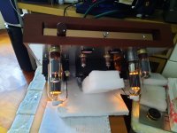
After making a new OPT, the diy tube amp is working now. However, there are some adjustments that I want to figure out.
1. The new OPT spec is that its primary DC current is 130mA (nom), 190 mA(max). With this spec, does it mean that the max DC plate current is 190mA/2 = 95mA so that DC (+/- AC current) = 95mA (+/- 95mA) = 0 to 190mA(max)? (ideal case)
2. Currently, I set the 805 plate current to about 80 mA (allow some safety margin). Is it good enough?
3. Regarding the hum balance pot, I tried to tune it to reduce the hum at the speaker (as suggested by astoufer.) However, seems that there is no noticeable difference at the speaker. The hum level stays more or less the same. Any idea on this issue?
regards,
Attachments
- Home
- Amplifiers
- Tubes / Valves
- Some questions on 805 Tubeamp circuit design and testing