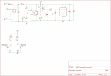
Greetings to all, recently i finished a project that was on my mind for a long time: A adjustable high voltage bench PSU PCB.
0-300V power supplies are few and far between. So i straight up cobbled something together. Based in part on an existing supply.
If you ask me why i did not use any preregulator circuits or switchers in this one: the answer is i wanted minimum noise.
The supply could be made to operate up to 400V but i'd have to re-spin the board for greater clearance and more mosfets.
If there is much interest, i can see if i can make something available.
Attachments


Yep, looks interesting, especially if it could deliver 400V and some more current (plenty of scope for bench-testing output stages).
Looks like the transformer and case will be the biggest $$ items? Was your trnsformer a custom build?
Looks like the transformer and case will be the biggest $$ items? Was your trnsformer a custom build?
For testing PA's I bought this and does what is says.
https://www.ebay.co.uk/itm/264564240112
Building your own sounds fun.
https://www.ebay.co.uk/itm/264564240112
Building your own sounds fun.
He is using an old TEK transformer, but you can hook up whatever you have at hand that gives you 300 VAC + 24 volt. You can even use a cheap 1:1 isolation transformer if you can live with a slightly lower max voltageYep, looks interesting, especially if it could deliver 400V and some more current (plenty of scope for bench-testing output stages).
Looks like the transformer and case will be the biggest $$ items? Was your trnsformer a custom build?
with two TO247 mosfets about 60-70W of dissipation.Interesting. How much power can it deliver?
Yep, looks interesting, especially if it could deliver 400V and some more current (plenty of scope for bench-testing output stages).
Looks like the transformer and case will be the biggest $$ items? Was your trnsformer a custom build?
I could look into that, but this is a linear supply, so it stresses the output devices quite hard at low voltage. One could add circuits to switch taps on the transformer or some other form of dissipation limiting, but this is just a linear supply with no frills.
Used transformer was a tektronix iron that had the right voltages for the job. The biggest outlay is the mosfets ($30) opamp and LT1010 DIP8 driver($10) pots ect, if you have to build this from scratch its allmost cheaper to buy something ready made, but it wont have the performance.
With a SCR preregulator one could improve efficiency however noise performance will be less.
Yes the current limit is adjustable, like the voltage, only thing it lacks is CC/CV Led indicators which i plan to add if i re-spin the board.Is the current limiter adjustable too? Can it withstand a direct short?
Measured noise under 100mA load is something like .5mV RMS if my fluke 175 is accurate.
Ive tested with a dead short a few times, and it survives that. Wether it will survive a dead short for long depends on the amount of cooling(You need 1K/W heatsink or less) and the current setting at the moment, because the supply will go into CC with no foldback mechanism.
Note that output capacitance was excluded from the PCB you need about 4u7 or 10uF on the output to maintain stability.
Last edited:
I am posting again in this topic because I was asked to design a slightly more powerful version for 0-400V 0-200mA
If there is an interest in this project I will do an improved design. The basic schematic works as advertised.
Cheers,
V4lve
If there is an interest in this project I will do an improved design. The basic schematic works as advertised.
Cheers,
V4lve
Yes, please.I am posting again in this topic because I was asked to design a slightly more powerful version for 0-400V 0-200mA
If there is an interest in this project I will do an improved design. The basic schematic works as advertised.
Cheers,
V4lve
Maybe it could be a dual 250V supply, with the capability of bipolar +/- 250V,
or else stacking them for a 500V single supply.
or else stacking them for a 500V single supply.
I have done some thinking since yesterday and it brings up the problems with going over 350V output in a Linear Fashion.
A hypothetical 0-450V 0-200mA supply would have a worst case dissipation slightly over 100W, and it would require three TO247 Linear N-Channel Fets like the IXTH30N60L2. But that are 17 USD deivces in qunantity. Some smartass is going to substitute 3 euro switching mosfets and those are going to blow up at 525V 60mA.
Also the heatsink will need to be about 0.3K/W to remain under 60C in a 30C ambient setting. The Fets will approach 100C junction temperature in that scenario.
I was floating the idea of using many old production fets made in the 1980's in parallel. My electronics supplier has BUZ80 Siemens TO220 800V 5A fets in original antistatic packaging for 60c each. You could put 10 of those in parallel and be confident they wont blow up anytime soon, because they are used within the safe area.
Another problem has to do with control. I need to research maximum voltage on some bourns ten turn potentiometers, because they will operate at 450V with respect to ground. and we dont want to be shocked by the knobs of our PSU!.
Another possibility is using flyback transformers. I have found a transformer made by feryster that can do 11-13VDC in. 450V 100mA out. Two of these could provide the required 450V 200mA at a fraction of the cost. those transformers are €7 each.
Cheers,
V4LVE
Since there are also requirements for lower voltage G2 supplies, negative G1 supplies, maybe the stackable 250V give flexibility?
I have been for a long time building the Sussex tube tester from UK Vintage Radio site, and it feels like it should be simple to have a flexible tube supply, and some small additional functionality to replicate the testing of an AVO tube tester (so gm is measurable, and ideally curves too in a long hand way).
uTracer 3+ manages 400V at 200mA, and there is a new version that supports 1A at 1000V. In this day and age should a unit having a programmable interface be the best option, so it can be controlled using lower voltage potentiometers, or even provide an API for integration into a test tool?
Here's a few thoughts on variable HV power supplies after my experience of using various types over the years in a DIY emission valve tester. I've used the one attached for several years but it eats mosfets. When testing old valves you get some that are a bit gassy, these have a habit of running away pulling big current and killing fets.
For really HV up to 450-500v you can't beat valves as the series pass element/s, but that means you have to use multiple valves with the requisite heat.Transistors designed for use as the horizontal deflection circuit in old TV's are less fault prone in my experience too.
Lastly switched zener diodes to select the voltage ( with a 10 turn fine adjustment pot) works better than a pot with 500v across it, though Tektronix used them in their 500 series scopes but they have a long shaft etc and are designed for HV.
Attachments
I was actually at one time working on a tube tester that could operate from a 18-28V battery pack supply. Thats why I got the 12V=>450V cores.
I allready made a flyback that does +-15V and -45V.
A buck regulator for filaments is very easy.
You could do the G2 supply with a boost converter.
Add a couple of 1W DC/DC bricks for LED panel meters and you have yourself a tube tester.
FETs get unstable with high DC voltages applied, they then fail due to the Spirov? effect?
One way to get around this is to use a cascode to share the voltage between two fets. I will draw something up for a simple experimentation supply later.
Cheers,
V4lve
- Home
- Amplifiers
- Tubes / Valves
- A SS bench power supply 0-300V -200mA for all your tube experimenting needs.