I have thought up a possible solution: There is a special optocoupler HCNR200 that can be used to build a low cost (€5 Bom) Isolation amplifier. I can use this to control the FET from the low side of the supply. In that way all the control electronics can be on the low side of the PSU supply. Its also fast enough( 1Mhz) not to disturb the Loop response of the OPA too much. I will use a LH0002 circuit made out of discretes to drive the fet.
Time to draw something!
Time to draw something!
Okay some updates. It was 26.5C/79F in my appartment for a while, and i found it hard to do anything at all. My plan with this project is to make a kit with the major parts for the build included.
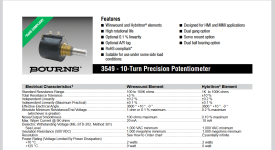
I have looked into the voltage ratings of 10 turn potentiometers, and the good ones made by Bourns are sometimes specified up to 1KV working voltage. There is no need to level shift the control voltages.
I have found a number of schematics for high voltage supplies with a floating reference, and i like the reference portion of this schematic: https://bygselvhifi.dk/projects/highvoltage/ Its a variation of the Elektor 82 power supply reference portion with LM723. It supplies +7.2V reference voltage and -5.6V for the opamp.
About the pass transistor secondary breakdown problem, my idea is to use a FET cascode made up of 2x4pc BUZ80 Mosfets, BUZ80 is a very old part from the 80's that i can get in quantities NOS, that has good SOA graphs and is from a time when FETS where not only designed for switching in mind.
For the output capacitor, i want to use a DC-LINK Film type capacitor, ESL and ESR of the output capacitor determines the stability of the PSU, and Film caps made for decoupling IGBT's have very good specs and don't age at all. I have found some surplus DC links 2u2/630V that i plan to design into the unit. My plan is to minimize the output capacitance.
I want to design the board so that a strip of 10x40mm Aluminium stock is used to interface the FETS with the heatsink.
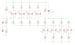
Attached a screenshot of the board progress. Current solution size is 100x180mm. A separate front panel PCB is also under consideration.
I have looked into the voltage ratings of 10 turn potentiometers, and the good ones made by Bourns are sometimes specified up to 1KV working voltage. There is no need to level shift the control voltages.
I have found a number of schematics for high voltage supplies with a floating reference, and i like the reference portion of this schematic: https://bygselvhifi.dk/projects/highvoltage/ Its a variation of the Elektor 82 power supply reference portion with LM723. It supplies +7.2V reference voltage and -5.6V for the opamp.
About the pass transistor secondary breakdown problem, my idea is to use a FET cascode made up of 2x4pc BUZ80 Mosfets, BUZ80 is a very old part from the 80's that i can get in quantities NOS, that has good SOA graphs and is from a time when FETS where not only designed for switching in mind.
For the output capacitor, i want to use a DC-LINK Film type capacitor, ESL and ESR of the output capacitor determines the stability of the PSU, and Film caps made for decoupling IGBT's have very good specs and don't age at all. I have found some surplus DC links 2u2/630V that i plan to design into the unit. My plan is to minimize the output capacitance.
I want to design the board so that a strip of 10x40mm Aluminium stock is used to interface the FETS with the heatsink.
Attached a screenshot of the board progress. Current solution size is 100x180mm. A separate front panel PCB is also under consideration.