Hello, I want to build a simple ( hopefully reliable ) Variable power supply for testing various electronics.
0 to 30v at 2A would be enough.
The easiest would be using LM317 ( I don't mind that LM317 won't go from 0 and instead 1.2v or something ) increasing it's output current with an " output transistor ".
Here is a quick google search on how to do that, most of them use PNP ( i don't really know why )
Is this the correct way to "convert" it to use NPN ?.
The only difference is current sink or source?
Please enlighten me.
Attachments
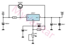
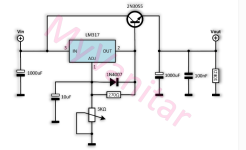
PNP gives a lower drop out voltage.
Also add reverse diodes across the 317 and the transistor. Don't forget the heat sink.
An input CRC filter after the diode rectifier helps with ripple reduction.
Might want to look at fig.23 here:
https://www.ti.com/lit/ds/symlink/lm317.pdf
Also add reverse diodes across the 317 and the transistor. Don't forget the heat sink.
An input CRC filter after the diode rectifier helps with ripple reduction.
Might want to look at fig.23 here:
https://www.ti.com/lit/ds/symlink/lm317.pdf
Last edited:
There are regulators that meet your specs and are still pretty cheap.
https://www.digikey.com/en/products/detail/texas-instruments/LM338T-NOPB/212669
https://www.digikey.com/en/products/detail/texas-instruments/LM338T-NOPB/212669

Transistors should be noncritical, just choose for enough voltage and current.
An isolated package will make the mounting easier.
Go with the smaller capacitor values that TI shows.
You only need large values for the input CRC filter after the rectifier.
An isolated package will make the mounting easier.
Go with the smaller capacitor values that TI shows.
You only need large values for the input CRC filter after the rectifier.
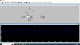
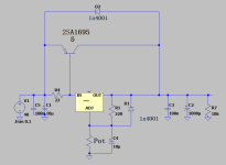
@rayma Thank you for your time, one more question, is this simulation related or something else,
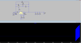
Might the transistors oscilate or something.
If the output capacitor is more then 10uF the output voltage looks like this.
Wouldn't I need bigger filtering caps on the output ? ( like 2200, 4700uF ? )
Might the transistors oscilate or something.
If the output capacitor is more then 10uF the output voltage looks like this.
Wouldn't I need bigger filtering caps on the output ? ( like 2200, 4700uF ? )
Attachments
@rayma oh you already said "
Go with the smaller capacitor values that TI shows.
You only need large values for the input CRC filter after the rectifier. " Does larger capacitors work as " capacitive load" as in audio amplifiers and make it oscilate ?.
So, I'll use 10uF tantalum maybe? for the " schematic" and large caps only for rectification after the transformer, bridge rectifier then .
Regulator circuits are amplifiers, and can have the same feedback instability problems.
Usually the instability happens for a certain range of load capacitance.
That is, just for an example, with a load capacitor of 5uF to 40uF, the regulator might oscillate.
Then you could use say 100uF or more to stabilize it. The simulation is only as good as the
device models though, so use some cut and try when actually building it.
I would not use tantalums myself, just good quality electrolytics.
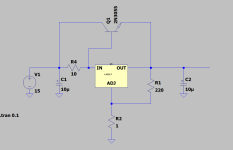
@rayma Using just one transistor instead of the " compound " as in TI schematic, works without oscillations now, ( at least in simulations ) regardless of load capacitance. Should I go this way then?.
I know the Hfe will matter here as , if I want 5 amps at the output with an 10 beta transistor it will need that LM317 should supply 500mA.
maybe use a darlington instead? to not drive as much as a current from the LM.
I know the Hfe will matter here as , if I want 5 amps at the output with an 10 beta transistor it will need that LM317 should supply 500mA.
maybe use a darlington instead? to not drive as much as a current from the LM.
Attachments

The 3rd picture at the very start is not desirable because you actually loose proper regulation.
and it could stress the base-emitter junction of the 2N3055 at switch-off.
The second schematic of the opening post is even worse. It has an impractically large minimum load current at low output voltage settings. For example, when you set the output to 3.3 V, it requires a load current of at least some 1.1 A to be able to pull the base of the NPN low enough, otherwise it loses regulation completely.
Anyway, the thread starter has already switched to circuits that could work.
@xXBrunoXx Lab supplies normally have current limiting. Do you require that or is it OK if the output transistor goes up in smoke when the output is shorted?
(As a compromise, you could just add a fast fuse somewhere and hope it blows before the transistor does.)
@MarcelvdG a fuse could work, Constant current would be nice for the load , lets say for charging lil ion cells , or limiting for whatever.
Just in case:
Elvee posted a small lab supply project, 0-30 V, 0-2A:
https://www.diyaudio.com/community/threads/lab-supply-on-a-shoestring.227538/
Elvee posted a small lab supply project, 0-30 V, 0-2A:
https://www.diyaudio.com/community/threads/lab-supply-on-a-shoestring.227538/
I would go for the single PNP. A Darlington pair again complicates frequency compensation.
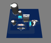
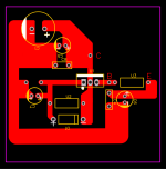
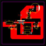
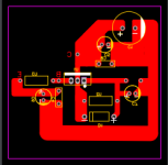
Made the PCB in EasyEDA, Any thoughts?.
Top view shows copper traces just for "clarity" actual traces are on the bottom, flipped.
1000uF 50v on the PCB , maybe I'll add another 2x 2200uf next to it , or is not " needed" ?.
Top view shows copper traces just for "clarity" actual traces are on the bottom, flipped.
1000uF 50v on the PCB , maybe I'll add another 2x 2200uf next to it , or is not " needed" ?.
Attachments
... just to point once more at @Elvee 's microlab i mentioned in post #16:Constant current would be nice for the load
it has voltage regulation from 0 - 30 V and variable current limiting.
Consider a ready made LM2596 DC-DC regulator board.
Add an LED Volt Amp display.
Power from a laptop brick for 20V,suitable for many purposes.
For higher voltage, add another supply in series (ensuring -ve outputs are not both grounded).
If both supplies are regulated, you have split supply for audio circuits.
Add an LED Volt Amp display.
Power from a laptop brick for 20V,suitable for many purposes.
For higher voltage, add another supply in series (ensuring -ve outputs are not both grounded).
If both supplies are regulated, you have split supply for audio circuits.
- Home
- Amplifiers
- Power Supplies
- I need a bit of help!