@fabrice63 Subjective impression of longer listening to music from these DACs 🙂 Tone coloring, listening fatigue, really very subjective. After a long time one finds that 100 people = 100 tastes 😊

Shhh🤫
Don’t tell anyone…..the price might jump even higher. 🤣🤪
https://www.ebay.com/itm/3642706880...sGheTUqSyi&var=&widget_ver=artemis&media=COPY
Edit:
I asked for any documentation for these chips, this was the reply I got. Form your own opinion.
“I don't have any documentation. This is old stock ADCOM”
Last edited:

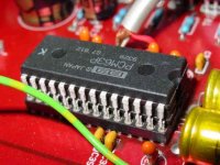
It doesn't look exactly like the original PCM1702,Shhh🤫
Don’t tell anyone…..the price might jump even higher. 🤣🤪
https://www.ebay.com/itm/3642706880...sGheTUqSyi&var=&widget_ver=artemis&media=COPY
Edit:
I asked for any documentation for these chips, this was the reply I got. Form your own opinion.
“I don't have any documentation. This is old stock ADCOM”
PHL = Phillippines and it is not K. By the way, I've seen other chips with that design, say PCM56, and that worked.
Meanwhile, the AD1856 got company in the form of the Burson V5. This is drastically better now. Which is to say, it fit him just right. It seems to me that twice as much detail now comes out of the speakers than with the OPA 1611. The spaciousness and depth of the sound image are excellent, as if it was not there. The duration of the tones has been extended. The sound balance is excellent, it sounds completely neutral. I just kind of miss the bass that the AD1865 has. I'm waiting for AD1860, it says "out for delivery" for days, it just doesn't arrive. 🙄
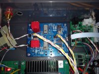
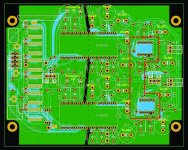
The second picture is the adapter for Miro PCBs dual OPA to 2 x single OPA. Point to point. It's not as nice as this by @Brijac, but it works. Hole raster is 2,54mm. The third picture is the position of the adapter on the PCB. I think it is clear that all capacitors must be soldered from below. Due to the small difference in the position of the two OPAs on the PCB (1,27mm) I placed all the pins in sockets on the Miro PCB and then soldered them. There is a bit of gap in the holes and the raster board is slightly slanted but it worked out that way even if it wasn't ideal.
The second picture is the adapter for Miro PCBs dual OPA to 2 x single OPA. Point to point. It's not as nice as this by @Brijac, but it works. Hole raster is 2,54mm. The third picture is the position of the adapter on the PCB. I think it is clear that all capacitors must be soldered from below. Due to the small difference in the position of the two OPAs on the PCB (1,27mm) I placed all the pins in sockets on the Miro PCB and then soldered them. There is a bit of gap in the holes and the raster board is slightly slanted but it worked out that way even if it wasn't ideal.
Attachments

Last edited:
I think this is a better option, at least K should be better than that one without the extra tag. These are my PCM1702-K. Neither of those two are made in the USA, that's why they are cheaper. Korea VS Phillippines, who knows which one is better? 🤣This is old stock ADCOM”
https://www.ebay.com/itm/362255965866?hash=item5458235eaa:g:kTQAAOSw7FRWWXRM&amdata=enc:AQAIAAAAwJycI6uTNlPpVF4Ujv6X0WNnQdf1fcWn7xyjg4adFIBw5d8/4xa4JttzlDj6BUF+SGFNASPTfVeTg5NVEP9VI8LN+tsK7BFSFNn6/E5v/vMDHhRte8iH6TbKYIqEOzeEEDr8aucEmBQ4CZMkmWlR7Kzftp5VxheB3Pa9pbSxFibhgN7FnJRRCIgomah8AWdVk+xHPLqK9VQvNj1Jv57kEh4AK8Z9/LR4NyCWJ5AVWKXUdFIuqXe2Ymgpg0oLI+nD/Q==|tkp:Bk9SR7CtitSJYg
You should listen to Muses02. And that can only be done through an adapter. Amazing how it fits together with the PCM63...t seems to me that twice as much detail now comes out of the speakers than with the OPA 1611.

Nah. there is no way it will play like this with Muses02 whatever you construct.Experiments with OPAs have been completed. Now only tubes and transformers follow, and skipping the shift registers.
I'm going to weld the cover on this DAC.🤣
mikorist,
How are you powering the Muses02? Is it the 5vdc on the analog side of the DAC or separate PS? If separate what voltage?
How are you powering the Muses02? Is it the 5vdc on the analog side of the DAC or separate PS? If separate what voltage?
Well, my joy was shortlived as I have no sound from the DAC anymore. I switched back and forth between a toslink board and the miniDSP USBStreamer. Both were working and had sound coming out of the DAC. The toslink board was being powered from the same 5V supply as the logic chips. I changed it to a 9V battery supply and it worked. Then I swapped back to the USBStreamer and no sound. But I am not sure of the order of swapping exactly.Absolutely! I built it stock but have the D1 I/V ready to go 🙂… itch is strong
Didn’t get to listen long last night but first impression was that I felt relaxed
There was no AC signal with music playing on the 3k3 I/V output resistor, so I presume that either the DAC chip is toast or one of the logic chips. All the voltages to the pins are fine. Beyond that, I am not sure how to troubleshoot the TDA 1541 chip or the logic chips. I do have another 1541 but don't want to put it in there until I know what is wrong. Any help is appreciated. 🙏
How are you powering the Muses02? Is it the 5vdc on the analog side of the DAC or separate PS? If separate what voltage?
Yes. +- 12V separate power supply.We all made the same, +-12V separate power supply for the I/V stage.
I'm just waiting until we get the new PCB adapter. That I can directly solder Muses02 to the PCB for better contact.
I also have 1K5 0.4W Charcroft Z-Foil Resistors (R8 and R9) and Mica Capacitors 82pF 500V 1% (Mouser No:598-CD15ED820FO3F) as
C31 and C36.
It remains to determine the value of C43, C44 through measurements. . .
@ra7 DAC chip should not be damaged.
Start with controlling all voltages directly on the DAC pins, be very careful not to short anything, (pin 28=5V, 26=-5V, 15=-15V)
Check voltages on the I/V opamp pins.
Measure +5VD voltage on all digital IC capacitors.
Do you have a digital analyzer to view data stream on digital pins? If not, turn your multimeter and measure AC voltage on digital pins. Play music and measure digital pins on the USB streamer (measure on disconnected from DAC and then on connected with DAC). You should see some AC voltage on your multimeter while playing music. Then measure digital pins on DAC chip if there is some AC voltage (pins 1, 2, 3, 4 with the GND pin 14).
🙂
Ок, I got it! I will look the same wires. Thanks.Here, for example, I use this kind of wire for wiring, 20AWG. I just got it locally, much cheaper. This is too expensive, especially the postage is killing.
https://www.ebay.com/itm/183870959890?_trkparms=amclksrc=ITM&aid=1110006&algo=HOMESPLICE.SIM&ao=1&asc=249388&meid=fab2e60c9f0c46a7b12b784a0864265a&pid=101195&rk=2&rkt=12&sd=174473760334&itm=183870959890&pmt=1&noa=0&pg=2047675&algv=SimplAMLv11WebTrimmedV3MskuWithLambda85KnnRecallV1V2V4V6ItemNrtInQueryAndCassiniVisualRankerAndBertRecall&brand=Thermax&_trksid=p2047675.c101195.m1851&amdata=cksum:183870959890fab2e60c9f0c46a7b12b784a0864265a|enc:AQAIAAABUOd1QM8gHEn%2FqSiYADGcz5pjtAjwq95dcmOo3rE8%2BcCWMXgqHrjq9Cbvs%2FFWhUTSatbJRDVCaYFnw81O0kQ%2Fgjj8V%2BTBXhaGVZNQFGW8UdOMlZlVFKakkZwYUyywM8LvVJFSur5S%2FOptMBNKmGa%2F7lWiqYYYZxpur0rN5PIfk2vnbPFs06pmL2dcBa0EZBV5kPn7uXZFBNbQdrob8e7b%2BwBTvoZ7kWa7pHibPjqPv7e9p%2BGFXBV9S4ZlOqN1cBs1RrLcwDIS4L8vdMC%2Fi7wO8zYxN6%2BdMdhrajK2vSQnMPdVKlH3CKRn1fm4NPq9PYx1YeZfcwUW6q5VsSIEORMKNvL5rqr6M8VwbBT4OQvD1FQQmV50%2BkA7sdYJ5bLkzwwARUBJvfCowKEtkeUp5dFR6uxYOogPuNpxxFj7nNX0f8QsWxU3CZ2%2B2C1K2bNgpWvEYw%3D%3D|ampid😛L_CLK|clp:2047675&mkevt=1&mkcid=1&mkrid=711-53200-19255-0&campid=5336770878&toolid=10001&customid=69111X1517312X237dfcb201beefcbb9ba90627f4e212d
I think that any DAC chip that has an Iout can be stacked on top of each other. Just disconnect the output pin from the internal OPA if there is one (AD1865, 1856, 1860, PCM56...). The result is a higher Iout, so the I/V resistor must be reduced.
I currently have 8xPCM1794A (4L+ 4R) in parallel. Iout is impressive, does not require an active I/V stage.
I currently have 8xPCM1794A (4L+ 4R) in parallel. Iout is impressive, does not require an active I/V stage.
Don't do the mistake, look at this thread:https://www.diyaudio.com/community/threads/pcm63pk-in-piggy-back-mode.51032/
6sn7 insted od OPs. RIV 33R (not this picture). I'm 🙂.
- Home
- Source & Line
- Digital Line Level
- DAC AD1862: Almost THT, I2S input, NOS, R-2R