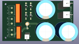
30cm 24V blue led strip connected to C3. Obviously you have to remove the plastic cover.


Here you can find almost all my recent builds:
https://www.flickr.com/photos/194234898@N02/albums
Here you can find almost all my recent builds:
https://www.flickr.com/photos/194234898@N02/albums

Slow load variations. In my opinion yes. It would be nice to check with LTSpice although. But as far as I remember some experiments done in the past, due to short time of conduction of bridge diodes, delta V on the first C got to be significant to increase the conduction angle to get enough charge in each cycle.So a capacitor right after the rectifier does a better job of smoothing the load current variations instead of a resistor then capacitor right after the rectifier?
However it is OK if the load is relatively constant. As a matter of fact I use RCRC for my B1 buffer.
Last edited:
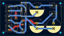
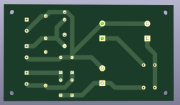
I'm having a kicad learning journey, trying to design a PCB for the 6L6-designed PSU. I use kicad 7.0 and the freerouting plugin. I routed GND manually, had a go at freerouting, and moved some tracks to B.Cu to minimize vias. Would you guys give your opinion on my work ? I have a few issues :
Charles
- the DRC tool says the GND end at (-) of C3 is unconnected. I can't see why it says this, it is connected.
- should I use a copper zone for GND ?
- the C5 decoupling cap is not optimally connected (its GND makes a large back-round to join "output GND" on J2). Is that an issue ?
- what else do I miss ? any other hints ?
Charles
Attachments
- should I use a copper zone for GND ?
The autoroute did a decent job, but post hand optimization is always a good idea.
a discussion about gnd planes in audio https://www.eevblog.com/forum/projects/should-i-use-a-ground-plane-in-my-audio-frequency-pcb/
- the DRC tool says the GND end at (-) of C3 is unconnected. I can't see why it says this, it is connected
- the C5 decoupling cap is not optimally connected (its GND makes a large back-round to join "output GND" on J2). Is that an issue ?
- what else do I miss ? any other hints ?
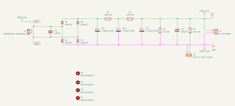
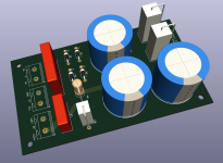
Thanks Frabor for your feedback. I moved things around to reduce the PCB size, and tried better routing. Results shown below. I played with a ground plane, but this is not an audio PCB, only a basic PSU with CRCRC filtering, so I see no real reason for a ground plane. The PSU is anyway followed by the regulation inside the turntable. Next is sending my work to an etcher and hope for the best. If things work well, I'll publish the kicad files.
Attachments
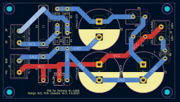
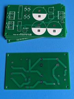
PCBway made it for a decent price, but I had to order the minimal qty of 5, kind of a stupid waste of resources when I need only one... anway so if it works well, I'll have 4 to give away for the price of packing and shipping.
I can report that this modification does work with the Technics SL-D3 also. The schematic is a few pages back, I removed Q1, Q2, Q3, D1, D2. I bridged across D1 with two jumper wires. The strobe does not work with this modification, no worries it was inaccurate anyway, operated by mains frequency. I can say the dynamic range or blackness of the table has increased. I am hearing little bits that were previously masked. I did replace the regulator with 6L6's circuit on a perfboard.

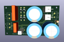
I was busy for the last two months and did not see your post. Layout looks good. I'll be following your testing.I have received the pcbs yesterday, however I'm leaving for holidays so the check and testing will have to wait. I won't share anything untested.
And I do belive your board can be considered an audio board since power supplies are a very delicate part of the Audio chain and any noise gather by them, can make it into the signal.
Ok, I have 2 SL-D3 tables and would love to see what else I can wring out of it. Was considering replacing the integrated patch cords/ground with something a little better. I know these are supposed to be very low capacitance but I'm sure there's gotta be a better alternative. Power supply seems like a great area to improve. I upgraded to an Audio Technica VM540 from a Shure M97xe which was revelatory! I'm currently rocking a pair of bridged ACAs and a Nutube preamp so how about another DIY kit?!? 🙂
Pass DIY Addict
Joined 2000
Paid Member
Sure, just when I've been making progress on my backlog of unbuilt projects 😉Wayne Colburn’s Pearl 3 phonostage is going to be announced very soon.
The first thing you should do is move the power transformer out of the chassis.Ok, I have 2 SL-D3 tables and would love to see what else I can wring out of it. W
Even if you do not upgrade the PSU in any other way this alone will bring a huge benefit regarding noise and vibration.
And with SL-D2 & D3, Q2 & Q3 it's very easy to do it.
Hmmm... I wonder if I'll be able to use my Pearl 2 PS.Wayne Colburn’s Pearl 3 phonostage is going to be announced very soon.
Add SL-Q202 to the list. I've done it years ago. Improvement is quite evident.The first thing you should do is move the power transformer out of the chassis.
Even if you do not upgrade the PSU in any other way this alone will bring a huge benefit regarding noise and vibration.
And with SL-D2 & D3, Q2 & Q3 it's very easy to do it.
- Home
- Source & Line
- Analogue Source
- Technics SL-1200 DC Power Supply