Hello!
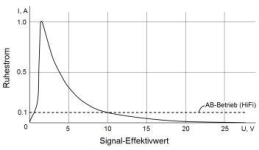
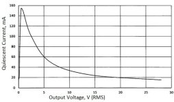
Class AB amplifiers are gradually being replaced by class D amplifiers. More and more old AB amps are being thrown away. But this is toxic waste for the environment. Alternatively you can significantly improve the sound quality of the first watt and keep using the old amps. The circuit is in the appendix. You can make from it a piggyback-board. It is connected parallel to the bias network. But before that, set the quiescent current to about 1A. After connecting the piggyback-board, set the quiescent current to 20mA with the potentiometer P1 of the piggyback-board. And that's it. When the small audio signal comes, the quiescent current increases to 1A and the amplifier works as class A. If the output power is more than 1 watt, the quiescent current drops and over 10 watts is less than 0.1A. And it continues to decrease at higher output powers.
Kind regards
Walter
Attachments

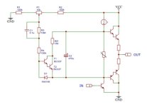
No, this is an additional circuit board. C2 must be connected to the bases of the power transistors, R1 to ground or to –V and R2 to +V.What you saying is to replace the amplifier board in the old amp for this one. Why?
This is just an abstract example.Besides, why have a Darlington output stage. They are prone to problems.
...When the small audio signal comes, the quiescent current increases......When the small audio signal comes, the quiescent current increases to 1A and the amplifier works as class A. If the output power is more than 1 watt, the quiescent current drops and over 10 watts is less than 0.1A. And it continues to decrease at higher output powers.
Kind regards
Walter
The quiescent current is set by the bias voltage. Can you explain how the (small) audio signal is changing this setting?
...If the output power is more than 1 watt, the quiescent current drops...
How is this controlled, and why 1W and not 2W, or 0.5W or 3.1415926W?
All this circuit does is drawing some current from the current source "I", a little bit more with a negative going signal, or a little bit less with a positive going signal. Less current from "I" is available for the bias circuit, causing the darlingtons to switch off at lower bias / q-current settings.
Can you show a simulation of this controlled bias / q-current behaviour?
Attachments
Ever heard of the EU RoHS and WEEE Directives...?More and more old AB amps are being thrown away. But this is toxic waste for the environment.
Sorry, the numbers are for my 200W amps. You're right, the quiescent current curve can be quite different.How is this controlled, and why 1W and not 2W, or 0.5W or 3.1415926W?
The measurement diagrams are in the appendix.
Attachments
Last edited:
The old old amps did not use lead-free solder.Ever heard of the EU RoHS and WEEE Directives...?
You just popped on here today with that statement?Hello!
Class AB amplifiers are gradually being replaced by class D amplifiers. More and more old AB amps are being thrown away.
Kind regards
Walter
I, as an old, seasoned professional repair tech, with over 45 years in the business, do not agree with that.
Class AB amplifiers are gradually being replaced by class D amplifiers. More and more old AB amps are being thrown away. But this is toxic waste for the environment. Alternatively you can significantly improve the sound quality of the first watt and keep using the old amps. The circuit is in the appendix. You can make from it a piggyback-board. It is connected parallel to the bias network.
This approach I have never seen before. Ask Mr. Bob Cordell or Mr. Nelson Pass (PM) :But before that, set the quiescent current to about 1A. After connecting the piggyback-board, set the quiescent current to 20mA with the potentiometer P1 of the piggyback-board. And that's it. When the small audio signal comes, the quiescent current increases to 1A and the amplifier works as class A. If the output power is more than 1 watt, the quiescent current drops and over 10 watts is less than 0.1A. And it continues to decrease at higher output powers.
https://www.diyaudio.com/community/threads/bob-cordells-power-amplifier-book.171159/
some efforts was made to avoid complicated bias adjust im class AB power amp stages in the last 50-60 years - check out this threads for various examples:
https://www.diyaudio.com/community/...automatic-self-biased-overview-wanted.164939/
https://www.diyaudio.com/community/threads/bias-servo-for-class-ab.307492/
https://www.diyaudio.com/community/threads/how-reliable-are-bias-servo-methods.360738/
https://www.diyaudio.com/community/threads/quad-405-updates-and-clones.358200/
P.S.: 1A quiescent current means 100W idle loss power in case of 100V supply voltage (+/-50VDC). Most integrated and power amplifiers made for 20-30mA quiescent current haven't therefore a sufficiently low thermal contact resistance between the transistor flansch (mounting surface) and the heat sink, even if this class A operation only occurs for a short time.
The only way this circuit can work is the trick with C1 and R3: for dc there is a base resistance of (≥) 10MΩ, and the darlington T1-T2 is pretty much off. With an ac signal more current flows: due to the µ1 capacitance there is only 155kΩ (( R1 + 1/2P1 // R2 + 1/2P1) + R4 ), and the darlington is 'modulated'. If the quiescent current is set high (from the current source "I" through the 'bias resistor' to the control vas) with no signal, then with a signal more current runs through this darlington and the quiescent current (due to the reduced bias) will decrease. And indeed with more / larger signal, more 'bias reduction'.Sorry, the numbers are for my 200W amps. You're right, the quiescent current curve can be quite different.
The measurement diagrams are in the appendix.
All settings and values of the components are variable, so lots of calculations to find the right values for a particular design.
Exactly!!!The only way this circuit can work is the trick with C1 and R3
There are many patents. My claim was rejected, despite the special case: https://patents.google.com/patent/DE102020005879A1/encheck out this threads for various examples
I can say nothing of the given circuit but i do know that Allen Wright says he made a good living in the early days adding CCs to amplifiers like the Phase Linears.
My tech (Duo) did just such to my Hitachi (or Toshiba) built SEARs 150w AB dual mono amplifier.
dave
improve the sound quality of the first watt
My tech (Duo) did just such to my Hitachi (or Toshiba) built SEARs 150w AB dual mono amplifier.
dave
This is a very interesting idea and you've made it elegantly simple and concise, but I think I see why the patent was sadly rejected.
During the late '60s, there was quite a scramble among engineers in Japan to solve the issue of transitory (crossover) distortion arising in the zero-crossing region, where transistors were most non-linear. The goal was to create non-switching amplifiers, laborious efforts to give the benefit of class-A operation while retaining the distortion cancelling benefits of class-B. Some were very successful, but they were also using other clever technologies in conjunction with their own versions of variable state biasing.
The foremost performance issue an amplifier encounters (one which hasn't been thought out to accommodate the addition of this circuit) is, that high bias causes distortion to actually rise. The reason for this is gm-doubling. The voltage gain introduced by both devices now conducting this current at the same time in the middle of their output voltage range, adds high-order harmonics to the distortion residual in much the same manner as under biasing does.
Another issue is waste heat - a normal B or AB amplifier will not be equipped to handle this dissipation and it may shorten the service life of the parts. What others might miss, is I believe you already had it in mind that the circuit needs to be set for the specific amplifier.
If optimized for its own amplifier, this circuit may work well.
Here you should actually pay attention to the temperature of the heat sink. If this becomes too high (>60°C), the circuit can no longer set the quiescent current to a minimum during the pauses. Alternatively, you can try using a Temistor instead of R6. This should be mounted on the heatsink of the output transistors.If optimized for its own amplifier, this circuit may work well.
Thank you for the comment!
Best regards
Walter
maybe a combination with this auto-bias approach helps
https://web.archive.org/web/20100729011121/http://home.tiscali.nl/data.odyssey/AutoBias.html
https://web.archive.org/web/20100729011121/http://home.tiscali.nl/data.odyssey/AutoBias.html
- Home
- Amplifiers
- Solid State
- Improvement of old AB amplifiers